Introduction
The NaxGCC is a GameCube-style controller built on the PhobGCC.
Like the PhobGCC, the NaxGCC uses hall effect sensors instead of potentiometers for stick input. Additionally, it connects directly to the console via USB, by pretending to be a GCC adapter with 1 controller (itself) connected. This eliminates one additional layer of polling, and thus reduces perceived latency and improves input consistency. The NaxGCC also features a special "input consistency mode" that even further improves input consistency, beyond what is delivered by any other controller / adapter.
If you're looking for support or want to chat about development for the NaxGCC, feel free to join the matrix chat at #naxgcc:naxdy.org.
The complete source code of this documentation is hosted at https://git.naxdy.org/NaxdyOrg/NaxGCC-Doc. Feel free to contribute to it, if you feel like something is missing or could be improved.
Key Aspects
Click on any of these to expand.
NaxGCC has all the important PhobGCC features.
The hardware of NaxGCC is directly forked from PhobGCC's, meaning it benefits from the same improvements over a "regular" GCC, most importantly the fact that it uses hall-effect sensors instead of potentiometers for reading your stick positions.
Furthermore, large parts of its firmware have also been taken from PhobGCC's firmware, such as the snapback filter, cardinal snapping, and notch remapping to name a few. If you're used to calibrating a PhobGCC, you will have no trouble here.
Provides both the lowest latency of any Switch controller, as well as the best input integrity.
Because the NaxGCC connects directly to the console via USB, it already outperforms any controller that has to go through an adapter in terms of input latency.
Further, the NaxGCC has a special "input consistency" mode (enabled by default), which ensures a input accuracy, compared to for any other controller (worse if there is an adapter in the mix, with the exception of the Lossless Adapter).
For details on how it works, have a look at the Input Consistency Modes.
Compatible with Phob hardware.
The NaxGCC firmware is compatible with regular Phob 2.0 boards (those using an RP2040 microcontroller), since it's originally forked from the PhobGCC project. This means that if you are willing and able to slightly modify your controller shell to allow a micro USB cable to connect to your Phob board during play, you can turn your existing PhobGCC into a NaxGCC at no extra cost!
What to find here
This book is the central source of information when it comes to the NaxGCC. Anything from user guides to information for hardware manufacturing / modding can be found here.
On Polling and Input Consistency
This is a rather technical document about USB polling, input latency, and the issues that arise with input consistency. If you only care about the NaxGCC's solutions to this problem, and not the background knowledge, you can skip ahead to the Input Consistency Modes section.
"Input consistency" and "input integrity" are used interchangeably in this document, and refer to the predictability with regards to the frame on which your input will come out.
General Info
The vast majority of human interface devices (HIDs) transmit their states over USB using a technique known as "polling". Essentially, these devices (clients) advertise themselves as supporting a certain polling interval/frequency to whatever device they're attached to (hosts). The host then polls the client at the desired frequency, or at a lower one (= not as often, = more slowly) if the host doesn't support the client's desired frequency.
The Nintendo Switch supports polling USB devices at up to , or once every . A game running at takes to draw a frame, meaning with a polling rate of , a USB device would be able to update its state up to 3 times per frame. Notice how I said "up to", because this is where things start to get wonky.
The reason it's "up to 3 times" and not "3 times, period" is because the USB polling and the game's frame draws are not multiples/divisors of each other, which causes them to continuously shift their offset to one another. Even a polling interval of would be perfectly sufficient, provided the host polls the adapter right before the frame is supposed to be drawn. Due to technical reasons, this is not possible however, so we are stuck with two asynchronous intervals: Polling & frame draws.
even if the host didn't poll the adapter right before the frame is drawn, it would still be fine, because as long as the polling interval is a divisor of the frame draw time, at least input integrity would be guaranteed, even if latency could still be variable depending on when your device was plugged in
Input Integrity
Now, what does this mean for your input integrity? Essentially, in a system where polling intervals are not multiples/divisors of each other, the time window in which your inputs are guaranteed to come out on the frame you'd expect them to is equal to where is the time it takes to draw a frame () and is the polling interval (). So, on the Nintendo Switch, where USB polling is locked and frame time of Smash Ultimate is , our window of time during which inputs are guaranteed to come out on the expected frame is
This then means that during the first of a "frame capture window", your input is guaranteed to come out on the frame you'd expect (the one whose frame capture window is currently open). For any input, the probability that your input will arrive at the expected frame, for any that is the time elapsed (in ms) since the start of the frame capture window, is . As you can see, for , and for .
In plain English, with a game running at and USB polling at , you have an (slightly more than half a frame) window where your inputs are guaranteed to be consistent, everything outside that window is RNG to varying degrees, whether your input will be delayed by a frame or not.
Now, using this we can calculate the overally probability that any input may be delayed by a frame, assuming a uniform distribution of inputs within the frame capture window. As we discussed before, for any , and for any . Since the probability that your input is delayed increases linearly the closer you get to the end of the frame capture window, we can establish that the average of all where is , and we can calculate the overall probability that your input is coming out on the expected frame like so: . This means that, in turn, every input you make has a chance of being delayed by a frame.
However, that's not the end of it...
Joybus
See, the math above assumes that the GCC adapter is the device providing the inputs to the console. However, it is only a middleware, and the true source of your inputs is your controller. The GameCube controller interacts with the GCC adapter pretty much the same as with the OG GameCube, using the joybus protocol, which is the same protocol that N64 controllers use. And its age shows, it doesn't have differential signalling, checksumming, or any of the other goodies other, more modern protocols (like USB) have.
But worst of all, it comes with yet another polling rate. Originally, the joybus protocol is polled at intervals, which would be catastrophic in this case. Luckily, the original GCC adapter made by Nintendo appears to poll at instead. Still not great, but better. Now, you might be thinking to yourself "but Naxdy, is less than , so surely this is a good thing?" well yes, but no. It would be a good thing, if the GCC could be connected to the Nintendo Switch directly, but it cannot, it has to go through the adapter, which has its own polling rate of 8ms.
So, you end up with a system with three independent polling rates: The Switch polls the adapter at intervals, and the adapter polls the controller at intervals, and then the controller has whatever scan rate it has (Phobs have a scan interval FYI). Now, remember how the time frame in which your input is guaranteed to come out on the expected frame was , but what about a system with multiple polling rates? Well, in this case it's where is the number of individual polling rates and are the individual polling rates (in ms).
Again in plain English, if you have multiple polling rates, the frame window in which your inputs are guaranteed to come out on the frame you'd expect them to, is the total time of the frame window minus the sum of all polling rates. So, let's do some addition and subtraction for our use case here: . That's less than half a frame!
This is how it is when you're playing with a PhobGCC (the best GCC currently available) on a first party GCC adapter from Nintendo. Note that third party adapters may very well be much worse than this, because they could poll the GCC at an even lower frequency (= more slowly).
BONUS QUESTION: What if the sum of all polling intervals is larger than the frame time window, i.e. ? That's right, in this case your inputs are always RNG! (good thing that's not the case here though)
The Solution
Since the NaxGCC connects directly to the console and eliminates the joybus protocol entirely, there is no second polling rate. The scan rate of the NaxGCC's sticks is , and the buttons are scanned as quickly as the MCU allows (I've measured as the average ceiling of the time, with the worst outliers being ). While not quite reaching the window length, the sticks have a window of guaranteed input integrity, and the buttons are getting fairly close to at worst (more than half a frame).
This isn't the end of it though. NaxGCC connecting directly to the console brings another advantage with it, namely we can "trick" the console into sampling the controller at a different interval altogether, one that works to our advantage. We can actually pretend to be a "laggy" USB device, by artificially introducing a variable delay in order to ensure the controller actually sends its button state to the console every instead of every . Why ? Because is a divisor of (the game's frame draw time), meaning the controller will be polled exactly twice as often as the game updates, and eliminating the chance of the polling intervals and the game's frame draw cycles offsetting to your disadvantage. This ensures that if you press and hold a button for (exactly 6 frames), it will always translate to 6 frames in-game (with polling at , there is a chance of it registering as 5 or 7 frames instead, as we established above).
unfortunately, due to real world limitations like timing jitter, this is not always the case, but it is the case of the time, see below for more info
The Experiment
So, what real-world impact does this have? I created a test in which I have the NaxGCC press and release a button, both in intervals. Meaning the game should register 6 frames held, 6 frames released, 6 frames held, and so on. I used the training mode modpack to measure the exact number of frames the game actually recognizes the button as held / released. I let this test run for 10 minutes and recorded it to a video, then used a python script to go through every 6th frame and record what the game actually registered using optical character recognition.
When in "OG controller" mode, the inputs were about accurate meaning of the time, the game registered 5 or 7 frames held/released when it should have been 6. This is in line with our math from above. In "input consistency" mode, the accuracy was at ! So, with a NaxGCC, not only do you get the lowest latency possible, since you're eliminating any sort of middleware in form of an adapter, but you also get the highest input integrity possible.
The original full-length videos of the experiment are saved and uploaded to my YouTube channel, in case you'd like to cross-check the results:
Repetition of this experiment is important, because in theory, it is possible to get "lucky" by plugging in the controller during the first of a frame capture window, and then never unplugging it, which would result in a theoretical accuracy. However, this is not a realistic scenario, and the experiment has been repeated multiple times to ensure that the results are consistent.
Input Consistency Modes
The NaxGCC features three separate input consistency modes, which can be cycled through during controller configuration.
Regular Mode
In regular mode, the NaxGCC will not attempt to modify the polling rate of the controller, and will instead send the controller's state to the console as soon as it is requested. This is the same behavior as the vast majority of other USB controllers and adapters when connected to the Nintendo Switch. This mode is not recommended for competitive play, as it carries a chance of your inputs being misinterpreted (see Input Integrity for details).
PC Mode
Same as Regular mode, except it asks to be polled at 1000Hz instead of 125Hz. This is useful if you're planning to use your controller on pretty much any device that isn't the Nintendo Switch. This mode carries the lowest latency, so if the device you're connecting to supports it, it is recommended to use this mode.
This is not recommended for use on the Switch, because it carries no benefit over Regular mode, and may actually lead to incompatibilities with other connected devices.
Consistency Mode
In consistency mode, the NaxGCC introduces a variable delay in order to wait responding to a poll request from the console until exactly (half a frame) have elapsed since the last status update. This ensures that the controller is polled exactly twice as often as the game updates and (nearly) eliminates the chance of your inputs being misinterpreted. This is the recommended mode for competitive play, and is the default mode for the NaxGCC.
While this is not exactly in-spec behavior for a USB device, it is still within the realm of what is generally considered to be "acceptable" with USB, and has been extensively tested to ensure that it does not cause any issues with the console.
"Super Hack" Mode
In "super hack" mode, the NaxGCC abstains from responding to the console's poll requests until the controller state has changed, and at least have elapsed since the last poll request. This ensures that, for inputs made more than apart, the latency is minimized, since the state is immediately dispatched to, and interpreted by, the console, at a slight cost to input integrity for inputs made less than apart.
"Super Hack" does not refer to this being a hack that is super, but rather something that is super hacky, since this pretty much out of spec behavior for a USB HID. However, it works!
NaxGCC Buying Guide
So you want to buy a NaxGCC, but you may not know what to look for, and you may not know how experienced the seller is at making them. Since the NaxGCC is very similar in assembly to the PhobGCC, generally speaking, if you know a seller is experienced at assembling PhobGCCs, you can probably expect them to make a good NaxGCC as well.
However, it is still important to know what to look for, especially if you're buying a used controller, in which case you may not know who assembled it at all.
This guide aims to show you what to check for, ideally before you buy. If buying in-person, ask the seller to take it apart to show you.
Also note that a Phob 2.0 can be turned into a NaxGCC, and in this case special considerations apply.
Easy Checks
This section is for things that are simple to verify without technical knowledge: whether it works, and important part selection.
Board Version
As of writing, the latest and only version of the NaxGCC board is 1.0.0. If you see a version number other than this, it could be an unofficial fork with changes that may or may not be beneficial. Ask the seller about it.
Conversion Boards
If the controller is a Phob 2.0 that has been converted to a NaxGCC, ensure that the seller made sufficient modifications to the controller shell to allow a micro USB cable to connect to the Phob board during play. Otherwise, you won't be able to actually connect the controller to your console.
Functionality
Obviously, the controller should work. To verify functionality, it is recommended that you use Smashscope. Have a look at the Getting Started section of our configuration guide for more information on how to set it up.
The L & R triggers should not depress fully as with an OEM controller, but instead feel similar to the face buttons, with a short travel distance. They should register at full 255 values when pressed. Rumble should function as well (assuming a rumble motor is installed). You can verify this by pressing Z on the Controller Test screen in Smashscope.
The sticks should not be very noisy or jittery when held off-center, but jitter between two adjacent values is acceptable. Notches should have repeatable coordinates when entered from the same direction, though they may have different coordinates if entered differently (clockwise, counterclockwise, straight from the center).
The controller should be set up so that it doesn’t have snapback. You can test this in game, but ideally you can run Smashscope and make use of its oscilloscope. Consult the Beginning Calibration section of our configuration guide for more information on what it's supposed to look like.
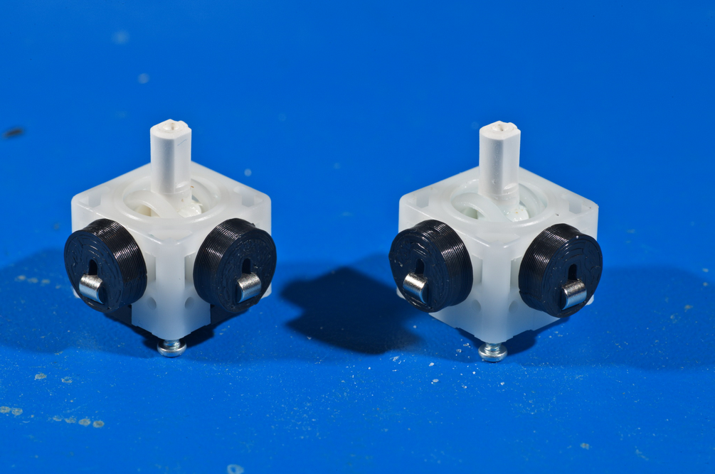
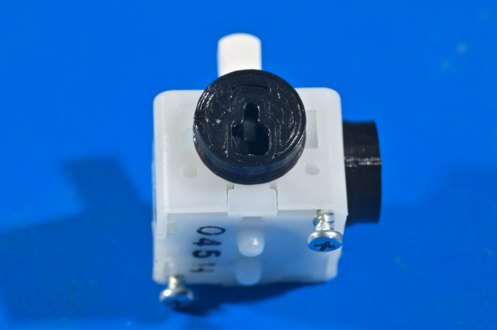
Stickbox
The stickboxes which contain the stick mechanism should be T3, which are entirely white plastic and mounted with two screws on the underside of each.
T1/T2 stickboxes, which have metal frames around plastic innards, are far more prone to wear and becoming loose. Additionally, they are soldered down, making them difficult to replace. This effectively limits the lifespan of a NaxGCC.
C-Stick Board
The C-Stick board should be a NaxGCC one with magnets, rather than an OEM C-Stick board with potentiometers. A Phob 2.0 daughter board can be used, and Phob 2.0.5 daughter boards are guaranteed to behave the exact same as a NaxGCC one.
The NaxGCC will not function with an OEM C-Stick board, or an earlier-generation Phob daughter board.
USB Cable
If the seller included a USB-C cable, ensure that it stays in place when inserted, doesn't fall out easily, and doesn't wobble. The Nintendo Switch is very particular when it comes to having a stable connection, and a loose cable can cause the controller to disconnect during play.
Ideally, you should be able to hang the controller from the cable, give it a good few shakes (not like Hercules, however), and it should not come loose. There should be some force required to remove the cable, and you should feel a click when inserting it. When wiggling the cable side-to-side, the controller should not disconnect (test this on an actual Nintendo Switch if possible).
Intermediate Checks
Here is where we begin evaluating the quality of the work.
Soldering Workmanship
Shorts
There must be no connections made between pads that are close together. You should be able to see green completely separating the solder.
Solder Joint Shininess
It is commonly believed that solder joints are supposed to be shiny, but that mainly applies to leaded solder (Sn63 or Sn60), not lead-free solder (such as SAC305). Most commercial products these days use SAC305 or similar due to regulations, but Sn63 is still often preferred by hobbyists for its ease of use.
Ask your vendor what kind of solder the NaxGCC you are evaluating was made with before judging the joint quality by how shiny they are.
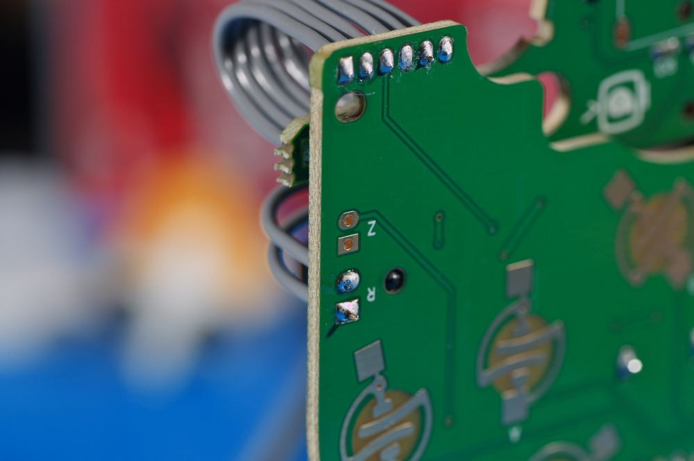
Solder Bonding
All solder joints should have the solder clearly sticking to both the component and the board in order to make a strong physical and electrical connection.
Solder Quantity
The entire pad on the board should be wet out with solder, but there ideally should not be enough solder to form a convex ball.
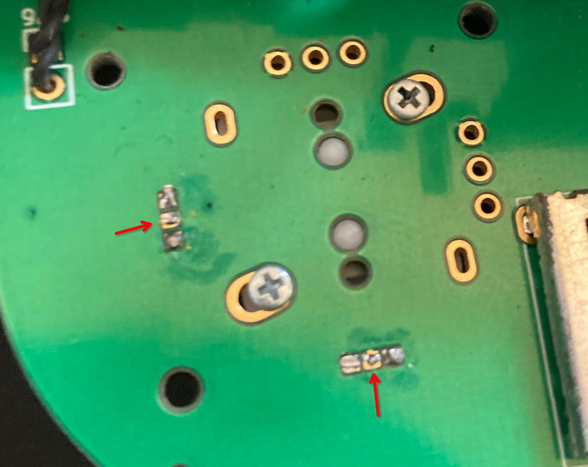
This is an example of a solder joint that has poor contact with the board and caused undesirable stick behavior.
Physical Workmanship
Stickbox Magnets
The magnet mounts on the stickbox should be firmly glued in place, and not come loose easily. A good way to test this is to use another magnet of the same strength and see if it can pull the magnet mount away from the stickbox. If it doesn't come loose, it's a good indicator that your controller will be able to sustain one or the other fall to the ground without the magnet mounts falling off.
Configuring Your Controller
This page contains all the information needed for configuring & calibrating your controller. Click on any of the links below to quickly navigate to a given section.
- Initial Calibration
- Configuration Options
Initial Calibration
The calibration process for the NaxGCC is very similar to that of the PhobGCC, but it is not the same. Furthermore, changes may be introduced in the future that further cause the processes to diverge, so it is best to refer to this document as your source of information, as opposed to the PhobGCC's docs.
Before You Start
When first plugging in your controller after flashing the NaxGCC firmware, you will notice that your sticks don't work at all (even if you flashed the firmware onto a previously-calibrated Phob 2.0 board).
Don't worry, this is perfectly normal and expected, as the sticks first need to be calibrated to your specific magnet / magnet-mount combination, as well as the layout of your controller shell.
Calibration is not very complicated and usually only takes a few minutes to complete. To start, you will need:
- your NaxGCC
- a computer with the Dolphin emulator installed
- a copy of Smashscope
- a USB-C to USB-A cable in order to connect your controller to your PC
Getting Started
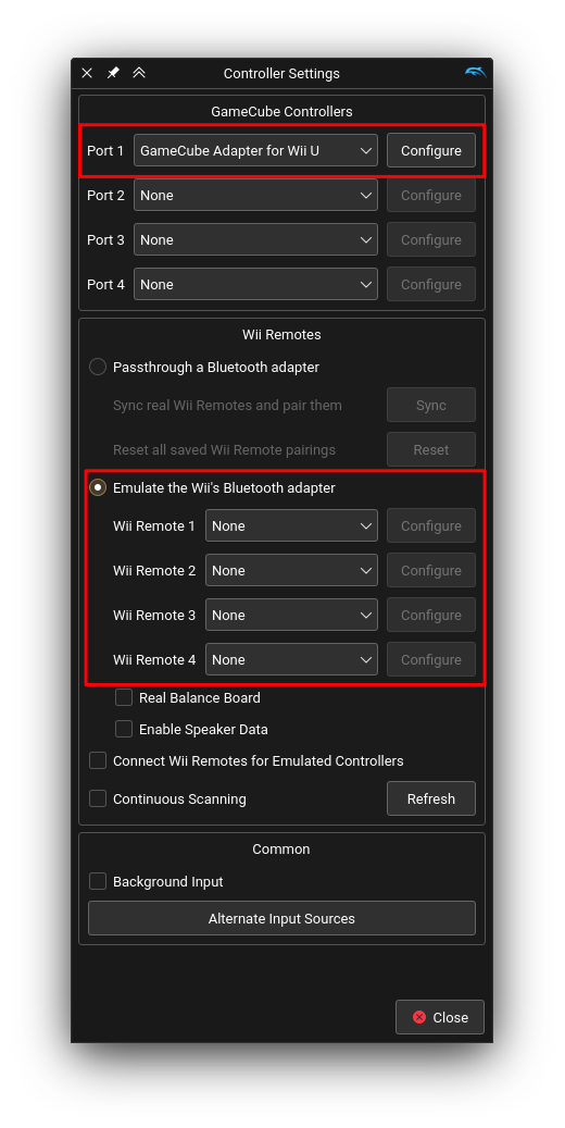
Before loading up Smashscope, ensure Dolphin's controller settings look like in the image below. Especially important is that you do not emulate any Wii remotes, as otherwise Smashscope will be unable to read your sticks!
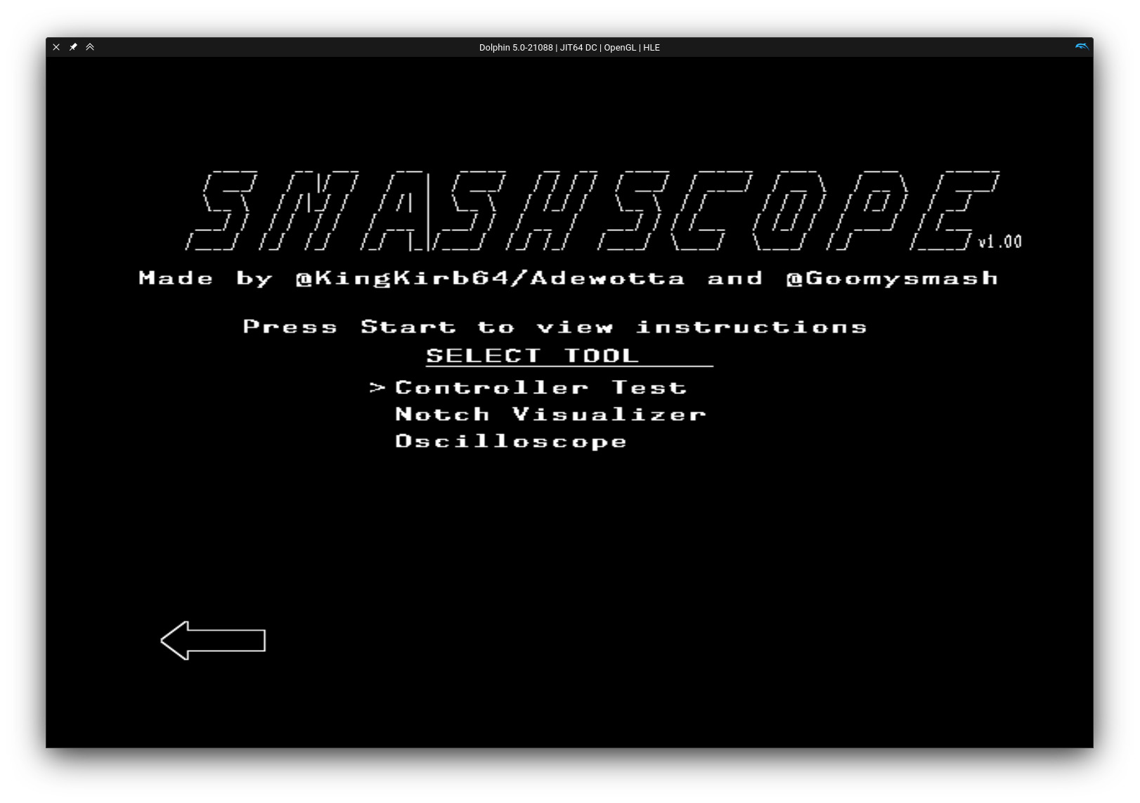
Start by powering up Dolphin and booting into Smashscope. You should see a screen similar to this:
If you haven't already, connect your controller now. Then press A in order to enter the "Controller Test" mode. You should see an image similar to this:
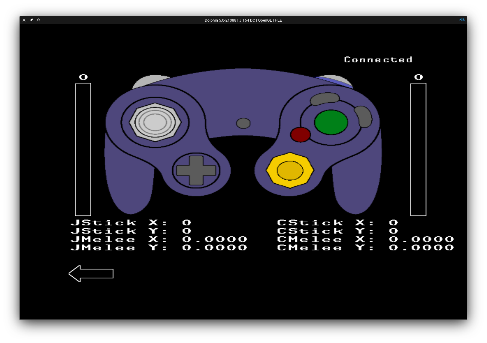
If your sticks don't look like this, but are completely out of whack instead, again, don't worry, this is to be expected. This screen will display any inputs you make on your NaxGCC in real time. Additionally, pressing the Z button will cause your NaxGCC to rumble.
Beginning Calibration
Now it's time to start calibrating your sticks. First, you will need to enter config mode by simultaneously pressing A+X+Y+Start. Your controller will freeze for one second while keeping the buttons held, and additionally pressing the triggers, before returning to its normal state. Now that you are in config mode, you have access to all calibration and configuration options.
Head on over to Stick Calibration and begin calibrating your control stick and your C stick. Once you've done so, it is highly recommended to determine whether your stick has any snapback (and how much), and configure the related snapback options in order to tone it down, or eliminate it entirely.
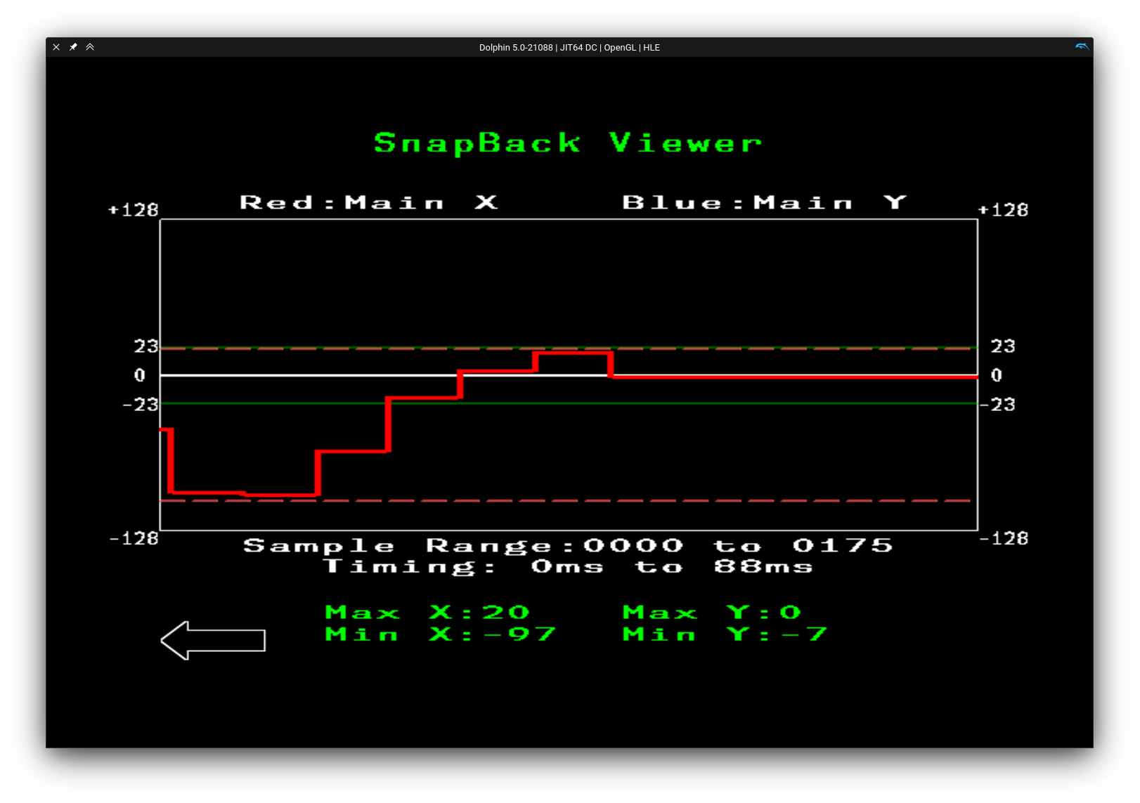
To do so, hold B to exit the "Controller Test" mode, and go into the "Oscilloscope" mode. In this mode, you can flick your stick left/right/up/down and see how far it extends into the opposite direction before returning back to center, giving you an easy-to-understand visualization of your stick's snapback. Your stick's X axis is displayed in red, and your stick's Y axis is blue.
For example, if you flick your stick to the left, ideally your Min X would be -100 (or another number far in the negatives) and your Max X would be 0 or close to 0. The more your Max X overshoots 0, the more snapback your stick has from left to right. The below screenshot shows a stick flick to the left with some snapback attached to it:
NaxGCC features a variety of snapback filtering options. Go ahead and give each one a try, you'll find that different options may have a bigger or smaller impact on your particular controller:
Adjust these in the "Controller Test" screen, then return to the oscilloscope to check the results.
Finally, after having tuned your snapback, you'll probably want to select your preferred Input Consistency Mode.
Configuration Options
These are all options you have while config mode is active. Config mode is activated by simultaneously pressing A+X+Y+Start.
When entering config mode, ensure you do not hold the A+X+Y+Start combo for multiple seconds. The reason is that the same combo is used to exit config mode, and keeping it held during config mode activation will cause you to immediately leave it again. It is recommended to enter config mode by holding A+X+Y and simply tapping Start.
Stick Calibration
Button Combo (Analog Stick): A+X+Y+L
Button Combo (C-Stick): A+X+Y+R
- Stick calibration has two phases: measurement and notch adjustment.
- During the Measurement Phase, you have the controller record the physical location of the corners of the gate and any modder-added notches.
- During the Notch Adjustment Phase, you can tweak the output angles of the notches you measured.
- You must complete both measurement and notch adjustment for the setting to be saved.
Measurement Phase
The first phase involves having the controller record the positions of the physical gate corners and notches as calibration reference points.
When in the measurement phase, the other stick's position (the one you're not currently calibrating) will alternate between the center and a position along the rim, starting with the cardinal directions. It shows you what you're supposed to do with the stick you're currently calibrating:
-
If the other stick is centered, let go of the stick you're calibrating and press
Ato record that position. -
If the other stick is not centered, move the stick you're calibrating into that position, ensuring that it is perfectly located within the notch, and press
Ato measure that position. -
You must measure all four cardinal directions (East, North, West, South) and all four diagonal directions or calibration will not work.
-
The first time you calibrate a controller that has modder-added notches, it is highly recommended to skip all the modder added notches and start with only the 8 primary directions.
-
Once you finish measuring all the notches (32 presses of
A), the stick should behave normally. You are not done calibrating. Proceed to the Notch Adjustment Phase below.If it does not behave as expected, see Measurement Phase Troubleshooting below.
Measurement Phase Troubleshooting
-
If the output of the stick you're calibrating is not accurate during this phase, do not worry. The previous calibration does not matter.
-
If the other stick is not alternating between being centered and circling all the way around the rim, you need to unplug and replug, and then restart Dolphin.
-
If after the measurement phase is done, the stick has one or two sectors that jump into another quadrant randomly, you probably mis-measured a notch. Mash
Aa bunch to finish the calibration and start again. -
If after the measurement phase is done, the stick output is completely haywire and jumping all over the place randomly, you may have let go of the stick before pressing
A. MashAa bunch to finish the calibration and start again.- Alternatively, if you have Firefox notches, try calibrating the main 8 directions only to completion, then go back and calibrate all of them.
-
If after the measurement phase is done, the stick output is backwards on one or both axes, you probably were trying to make the stick output match the other stick, instead of moving the physical stick into the notch indicated by the other stick. Mash
Aa bunch to finish the calibration and start again. -
If after the measurement phase is done, your stick does not perfectly move between
-100and100, but instead seems to be somewhat offset (either vertically or horizontally), you may need to ensure that the magnets you're using are mounted to have their polarity aligned. Consult the magnet mounting section of the hardware assembly guide for more information.
Notch Adjustment Phase
After the measurements are complete, this phase lets you adjust exactly where the non-cardinal notches are mapped to. This is useful, for example, if you want to ensure that you're getting up/down tilts when in one of the top/bottom corners, instead of forward tilts.
When in the notch adjustment phase, the other stick will stay along the rim and rotate along from notch to notch, starting with the diagonals. This indicates which notch is currently adjusted.
-
The position of the stick you're calibrating does not affect notch adjustment. The output is a live preview of how the calibration will be with your given adjustments, so feel free to move your stick around to see what it would be like.
-
Press
XorYto shift the output of the notch clockwise or counterclockwise, respectively.Note that you will only be able to actually observe the change when you're moving the stick to the notch that's currently being adjusted.
-
To discard your current modifications and reset to the default notch state, press
B. -
Press
Ato proceed to the next notch.
When the other stick's position returns to center, or resumes displaying the actual stick's position (which may be all over the place if it's not yet calibrated), the stick calibration is now saved.
Notch Adjustment Troubleshooting
-
If your notch coordinates are very inconsistent, try twisting the stick like a knob and see if the origin value shifts. If so, try gently tightening the screws holding the stickbox down; they may be loose.
-
If your notch coordinates have slightly different values when approaching straight from center compared to rolling clockwise or counterclockwise along the rim, this is normal (within two or three values).
-
If your notch coordinates cannot be adjusted to the desired value, check the other stick's coordinates to see if it's too far from the desired value. You can try recalibrating from the start and measuring it again, but it may not help. See a modder to get your notches adjusted if needed.
Smart Snapback Adjustment
Button Combo (Analog Stick): A+X/Y+Du/Dd
Button Combo (C-Stick): A+Z+X/Y+Du/Dd
This feature is currently unused for the C-Stick. While you can still adjust the values, changing them won't actually affect the stick's behavior.
Button combos for adjusting values for the C-Stick are the same as for the analog stick, with an added press of the Z button.
Increasing the stick Smart Snapback Filter adjustment doesn’t hurt responsiveness of the stick when moving away from the center. Increasing the value of this filter only makes it return to center more slowly.
-
Press
A+(Z)for your stick,X/Yfor your axis, andD-pad up/downto increase/decrease.- Example:
A+(Z)+X+Dusuppresses X-axis snapback more, andA+(Z)+Y-Ddsuppresses Y-axis snapback less. - When you change this setting, the current snapback filter settings are shown as the numerical coordinates on the stick you're adjusting.
- Example:
-
The scale goes from
-10to+10, and defaults to4.-
0completely disables the Smart Snapback Filter. This removes the rise time improvements, hurting dashdancing on the X axis, and you will have snapback. -
Positive values have strong rise time reduction that promotes fast tilt inputs into smash inputs.
Higher values have stronger snapback suppression.
-
Negative values minimize rise time reduction and make the stick behave more like an OEM controller.
More negative values have stronger snapback suppression.
-
Sticks usually need a setting of
4-7.9+is for special situations such as metal stick caps or lighter spring weights. -
If you have an OEM stick cap and snapback is still a problem, try setting the snapback filter to
0and check how far the snapback goes. If it goes past70, you may have to tame snapback by adding a bit of grease to the stickbox.
-
Press Du+Start while in config mode to display the smart snapback values on each stick.
Waveshaping Adjustment
Button Combo (Analog Stick): L+X/Y+Du/Dd
Button Combo (C-Stick): L+Z+X/Y+Du/Dd
Button combos for adjusting values for the C-Stick are the same as for the analog stick, with an added press of the Z button.
The Waveshaping filter stops the output from moving while the stick axis is moving quickly. This setting controls the threshold where that transition occurs.
This can be used to make short flicks behave more like a good OEM controller. This enhancement to flicks works best with an OEM spring or a Smalley L2 spring, not with lighter "slickbox" style springs, but you can crank it up and make it work at the expense of responsiveness.
- Press
L+(Z)for your stick,X/Yfor your axis, andD-pad up/downto increase/decrease- Example:
L+(Z)+X+Dustrengthens the effect on the X axis, andL+(Z)+Y+Ddreduces the effect on the Y axis. - When you change this setting, the current Waveshaping filter settings are shown as the numerical coordinates on the stick you're adjusting.
- Example:
- The scale goes from
0-15, and defaults to0.0disables waveshaping entirely.- Ideally, change both axes together.
Press L+Start while in config mode to display the waveshaping values on each stick.
Stick Scaling Adjustment
Button Combo (Analog Stick): L+A+Du/Dd
Button Combo (C-Stick): L+Z+A+Du/Dd
This feature has simply been ported over from the PhobGCC for compatibility reasons, but is not very useful for Super Smash Bros. Ultimate. It is recommended to leave this setting at its default value of 100.
Button combos for adjusting values for the C-Stick are the same as for the analog stick, with an added press of the Z button.
The Stick Scaling setting allows the user to adjust what value the stick can reach at the edge of the gate. Super Smash Bros. Melee has a unit circle that ranges from -80 to +80, OEM Gamecube controllers range from roughly -100 to +100, and the GCC protocol allows for -128 to +127. The NaxGCC, just like the PhobGCC, hard limits its own stick outputs to a range from -125 to +125, but this setting corresponds to what you get immediately after calibration.
- Press
L+A+(Z)for your stick, andD-pad up/downto increase/decrease- Example:
L+Z+A+Dustrengthens the effect on the C-Stick, andL+A+Ddreduces the effect on the control stick. - When you change this setting, the current Stick Scaling filter settings are shown as the numerical coordinates on the stick you're adjusting.
- Example:
- The scale goes from
82-125, and defaults to100.- This changes the physical distance to the rim of the Melee unit circle.
- At
82, the rim of the Melee unit circle is basically at the rim of the controller, requiring larger motions for things like smash attacks. - At
125, the rim of the Melee unit circle is much farther in, requiring smaller motions for things like smash attacks.
Cardinal Snapping Adjustment
Button Combo (Analog Stick): R+A+Du/Dd
Button Combo (C-Stick): R+Z+A+Du/Dd
This feature has simply been ported over from the PhobGCC for compatibility reasons, but is not very useful for Super Smash Bros. Ultimate. It is recommended to leave this setting at its default value of 6.
Button combos for adjusting values for the C-Stick are the same as for the analog stick, with an added press of the Z button.
The Analog Stick Cardinal Snapping setting allows the user to adjust the width of the window around the cardinals around which the stick will snap to perfect 1.0.
- Press
R+A+(Z)for your stick, andD-pad up/downto increase/decrease- Example:
R+Z+A+Dustrengthens the effect on the C-Stick, andR+A+Ddreduces the effect on the control stick. - When you change this setting, the current Cardinal Snapping filter settings are shown as the numerical coordinates on the stick you're adjusting.
- Example:
- The scale goes from
-1to6, and defaults to6.- At
-1the stick will snap away from the cardinal so that the stick cannot output1.0cardinals at all. - At
0, the stick will not snap to cardinals at all. This is equivalent to OEM cardinal behavior. - Between
1-6, the stick will snap to the cardinal from that far away in both positive and negative directions.
- At
Axis Smoothing Adjustment
Button Combo (Analog Stick): R+X/Y+Du/Dd
Button Combo (C-Stick): R+Z+X/Y+Du/Dd
Button combos for adjusting values for the C-Stick are the same as for the analog stick, with an added press of the Z button.
Axis Smoothing is just a simple low-pass filter similar to a capacitor on a vanilla Gamecube controller. Increasing this setting slightly reduces responsiveness. If you have the Smart Snapback Filter disabled, you can use this to suppress snapback, or use both in conjunction if your snapback is really strong (though in these cases, it's often better to try and solve the problem from a mechanical angle).
- Press
R+(Z)for your stick,X/Yfor your axis, andD-pad up/downto increase/decrease- Example:
R+(Z)+X+Dustrengthens the effect on the X axis, andR+(Z)+Y+Ddreduces the effect on the Y axis. - When you change this setting, the current Axis Smoothing filter settings are shown as the numerical coordinates on the stick you're adjusting.
- Example:
- The scale goes from
0-9, and defaults to0.0disables axis smoothing entirely.
Press R+Start while in config mode to display the axis smoothing values on each stick.
Rumble Strength Adjustment
Button Combo: A+B+Du/Dd
- Press
A+BandD-pad up/downto increase/decrease the rumble strength. - The scale goes from
0to11.9is roughly equivalent to an OEM controller's rumble.0turns off rumble entirely.
- When adjusting, the current rumble strength will be displayed on the analog stick's Y axis.
Input Consistency Mode Toggle
Button Combo: A+Z+Start
Cycles the input consistency setting through its three modes and displays which mode is currently active on the analog stick's Y axis:
-69: "Regular" mode, same behavior as any other USB controller connected to the Nintendo Switch. Not recommended.-42: "PC" mode, same as Regular mode, except the controller will ask to be polled at 1000Hz instead of 125Hz. Only recommended for playing on PC, or other consoles that actually support 1000Hz. Do not use this mode on the Switch, it will not work, and might even cause issues with other USB devices.42: "Consistency" mode, aims to improve input consistency at the cost of input latency compared to "regular" mode on the Nintendo Switch - default setting.69: "Super Hack" mode, aims to improve input latency at a slight cost of input consistency compared to "consistency" mode. Currently experimental, not (yet) recommended for tournaments.
For more information about the different input consistency modes, consult the Input Consistency Mode list.
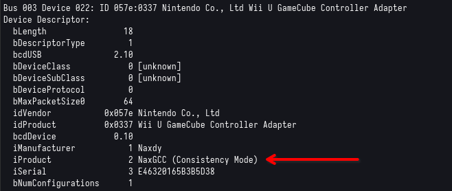
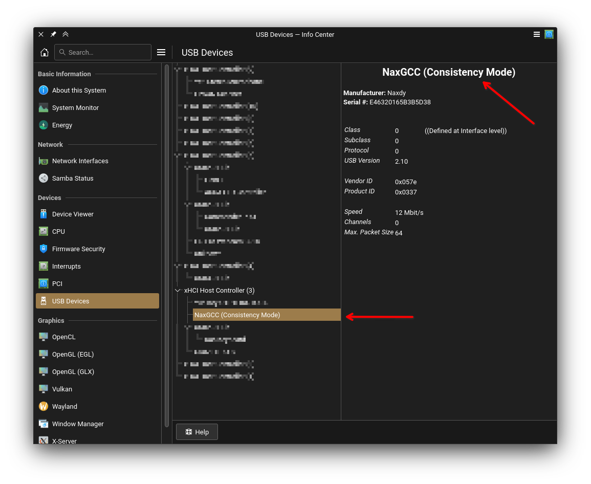
This setting will only become active upon unplugging and replugging the controller. The controller will then indicate the mode it's in by changing its device name. You can then use your operating system's device viewer to have a look at the device name and determine which mode is currently active. For example, under Linux you can run lsusb -v and look for NaxGCC:
Pro Controller Mode
Since: v1.2.0
Button Combo: Start while plugging in the controller
Makes the NaxGCC present itself as a Nintendo Switch Pro Controller instead of a GameCube adapter with 1 controller connected. While in this mode, pressing Z+Start will behave like pressing the home button on a regular Pro Controller. Additionally, pressing L will press both L and ZL at the same time.
If you unplug your controller, then plug it in again without holding Start, it will once again show up as a regular GameCube controller.
Switch firmware version 19.0.0 suffers from a known issue with GCC adapters (including NaxGCC, which pretends to be one). It is recommended to use Pro Controller Mode if you are on Switch firmware version 19.0.0. If not, it is entirely up to personal preference.
Display Values
Display waveshaping values on each stick: L+Start
Display axis smoothing values on each stick: R+Start
Display smart snapback values on each stick: Du+Start
Updating Controller Firmware
Keeping your firmware up-to-date is recommended to ensure you benefit from the latest features, fixes, and improvements to performance. New versions of the firmware are published at the official NaxGCC-FW repo's release page
Take care not to accidentally download the nightly release, as these are experimental and may not be stable, unless you want to be a guinea pig for new features.
Flashing your controller for the first time
If your controller is brand new and has never been used before, you will need to flash the firmware onto it. This is a one-time process, and you will not need to do it again unless you want to update the firmware.
Simply plug in your NaxGCC to your computer. It will show up as a regular mass-storage device, similar to a USB stick, or an SD card. Drag & drop the firmware binary (the file ending in .uf2) onto the device. The mass-storage device will disappear, and your NaxGCC is now ready to use!
Updating your firmware
If you already have a controller with firmware on it, updating is easy. Simply plug in your NaxGCC to your computer while keeping the A+X+Y buttons held. The controller will show up as a mass-storage device, similar to when you first plugged it in. Drag & drop the new firmware binary onto the device, and you're done!
Major firmware updates (e.g. 1.x.x to 2.x.x), WILL cause your configuration and calibration to be reset! For these updates, it is recommended to write down your config values for things such as snapback, stick smoothing, etc. before updating. Also make sure to set aside some time to recalibrate your sticks after updating.
Minor firmware updates (e.g. 1.0.x to 1.1.x) and fix updates (e.g. 1.0.0 to 1.0.1) will not cause your configuration to be reset, and you can safely update without having to recalibrate.
If holding the A+X+Y buttons doesn't work, e.g. because the connection was interrupted during the last flashing of the firmware, and the controller is stuck in a non-functional state, you must take it apart and press the BOOTSEL switch on the controller board itself. This is a small button located near the center of the board. Hold this button down while plugging in the controller to your computer, and it will show up as a mass-storage device. You can then drag & drop the firmware binary onto it.
Downgrading your firmware
If you ever need to downgrade your firmware, the process is the same as updating. Simply plug in your NaxGCC to your computer while keeping the A+X+Y buttons held. The controller will show up as a mass-storage device, similar to when you first plugged it in. Drag & drop the old firmware binary onto the device, and you're done!
The same rules as for updating apply here. Major downgrades will cause your configuration and calibration to be reset, while minor downgrades and fix downgrades will not.
JLCPCB Parts Ordering
This is an illustrated guide to ordering NaxGCC PCBs via the JLCPCB Board House.
JLC Ordering Process Overview
This is very important, or else you will get nonfunctional boards.
- Preorder the SMD components that are in limited supply, as listed below.
- These are not stocked by JLC but they are stocked by distributors; JLC will order them and keep them in your name until you order boards that need them.
- Once ALL OF THE PARTS come in, only then order boards with assembly.
- You may need to wait a week or more.
- Do not order boards before you receive notification that ALL of your parts are available.
- If you order boards before parts are available, then they will be assembled without the parts and they will not function.
- Wait for your boards to come in.
Pre-ordering SMD components
Since the NaxGCC board is fully integrated, all of the non-GCC components are soldered onto the board at the board house. Some of these may be out of stock, and as such need to be pre-ordered before you place a board order. Pre-ordered components take on average 2 weeks to arrive at the JLCPCB warehouse after you pay for them. If a component takes longer, you can contact JLCPCB support for a more accurate timeframe of arrival.
The following parts usually have low stock and pre-ordering them is advised:
These part quantities are for a single NaxGCC board. You need to multiply them by the number of boards you plan to order.
You can only order PCBs in quantities of 5, 10, 15, 20, 25, 30, 50, or more. Do not order SMD components for amounts other than these or you will either have unused extra parts or unpopulated PCBs later.
if you're planning on swapping out the Winbond chip for a different one, note that the serial number reported by the NaxGCC upon plug-in may no longer be unique
you need 1 more cystal oscillator per order you plan to place regardless of how many boards are in the order
Once you've clicked on each link and added the quantities you need into your cart, click the cart icon in the top right, go to the "Parts Manager Tab", to the "Order Parts" subtab, to the "Cart" subtab as follows:
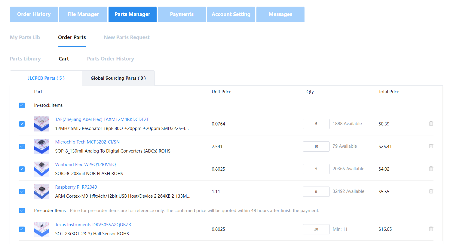
This is where you double-check the part quantities you've selected and make sure that they're all checked, even if in stock. Once you checkout, JLC will attempt to purchase those parts for you at the quoted price. If they end up costing more, they'll email you about supplementing the cost, and if they end up costing less, you will be refunded the difference. You can check the status of part orders in the "Parts Order History" subtab.
Some of the parts may be in stock and be available immediately. You must wait until ALL PARTS are available before proceeding. This may take one or two weeks.
Purchasing the NaxGCC board from JLCPCB
Once your pre-ordered SMD Components have come in (report as "Complete" in the parts order history), you may proceed to ordering boards. If they are not in, the parts will not be present on your board, and your board will not be functional.
Download the files available in the NaxGCC-HW git repo in the releases section as shown below:
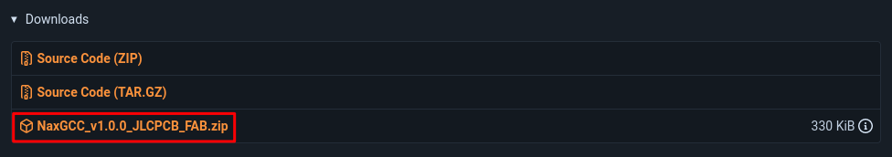
Make sure to redownload the latest even if you already downloaded it in the past, as occasionally we make changes to the components to account for stock shortages or changes.
Once you've extracted the files from the .zip, you should have three files:
- NaxGCC_vX.X.X.zip (the gerber files)
- NaxGCC_vX.X.X_bom.csv (the bill of materials)
- NaxGCC_vX.X.X_top-pos.csv (the component placement file)
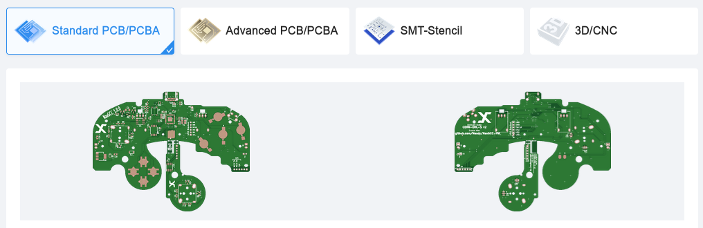
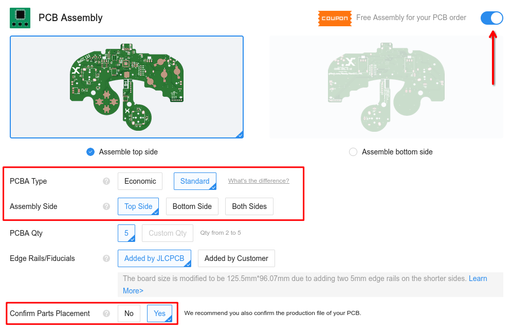
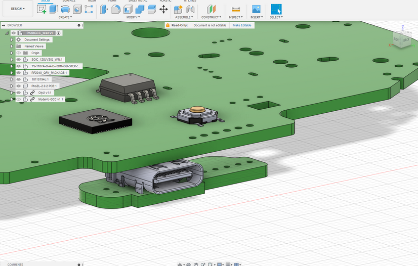
Click "Order Now" on JLCPCB, make sure you are set to "Standard PCB/PCBA" tab, click "Add Gerber File", and upload the NaxGCC_vX.X.X.zip. Once the files are uploaded, you should see the board process and then load in as shown below:
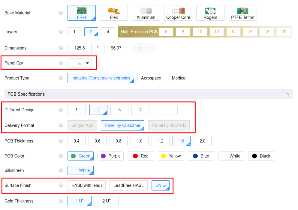
Once you've checked that the size is set to 96.07x125.5mm, you can progress with configuring it. The recommended settings are the defaults, setting your board quantity, setting "Different Design" to 2, and setting the Surface Finish to ENIG, as seen below:
Scroll down to PCB Assembly and toggle it on the right. Select Standard PCBA Type (Not available for large orders or colors), the top side, and confirm parts placement as seen below.
For large orders such as more than 50 boards or different colors, Standard Assembly is required. This attaches removable rails to the PCB at a significant extra cost.
If arranging group buys or purchasing in large quantities, we strongly suggest using Standard PCBA so DOA boards are less likely.
Click "Confirm" and then upload the NaxGCC_vX.X.X_bom.csv to the left and and the NaxGCC_vX.X.X_top-pos.csv to the right. Set the usage description to Research/Education/DIY DIY HS Code and click "Next". The text at the top of the next screen should look like the following with all 25 confirmed.

The important part is that it should read 26 parts confirmed. Don't worry about the 11 parts not selected, as these are parts that will be added afterwards in the assembly process (stickbox assemblies, face buttons, etc.).
After clicking "Next", you'll be presented with a view of the parts on the board. If this screen is corrupted, that's okay. The files are known good and this is just the website bugging out. You want to make sure there are no red boxes anywhere as those indicate missing components. Ideally, the top view should look something like this:
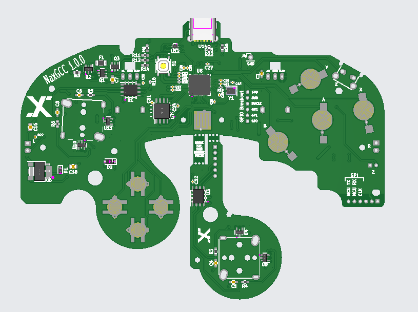
At this stage, don't worry if some components are in the right position, but rotated incorrectly. This should be corrected by JLCPCB later in the process, and this is why we selected "Confirm Parts Placement" earlier in the process, so you'll get to inspect the corrected parts placement before the order is put into production. You can then click "Save To Cart" and pay for your boards.
Later on, you will get a notification that the parts placement is ready for review. The corrected parts placement should look something like this:
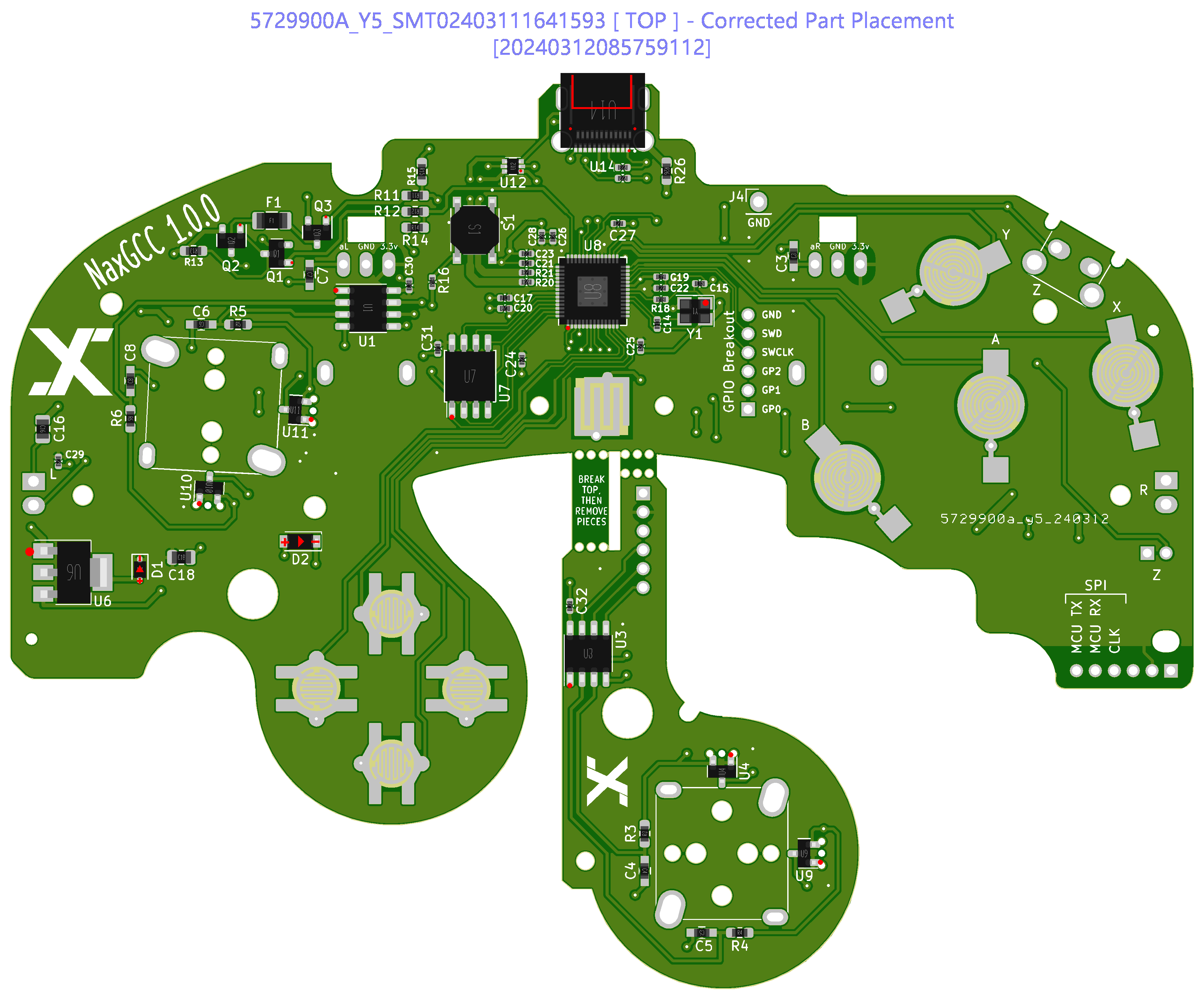
If everything looks good, go ahead and confirm the parts placement. Your boards will then be put into production and shipped to you as soon as they're done.
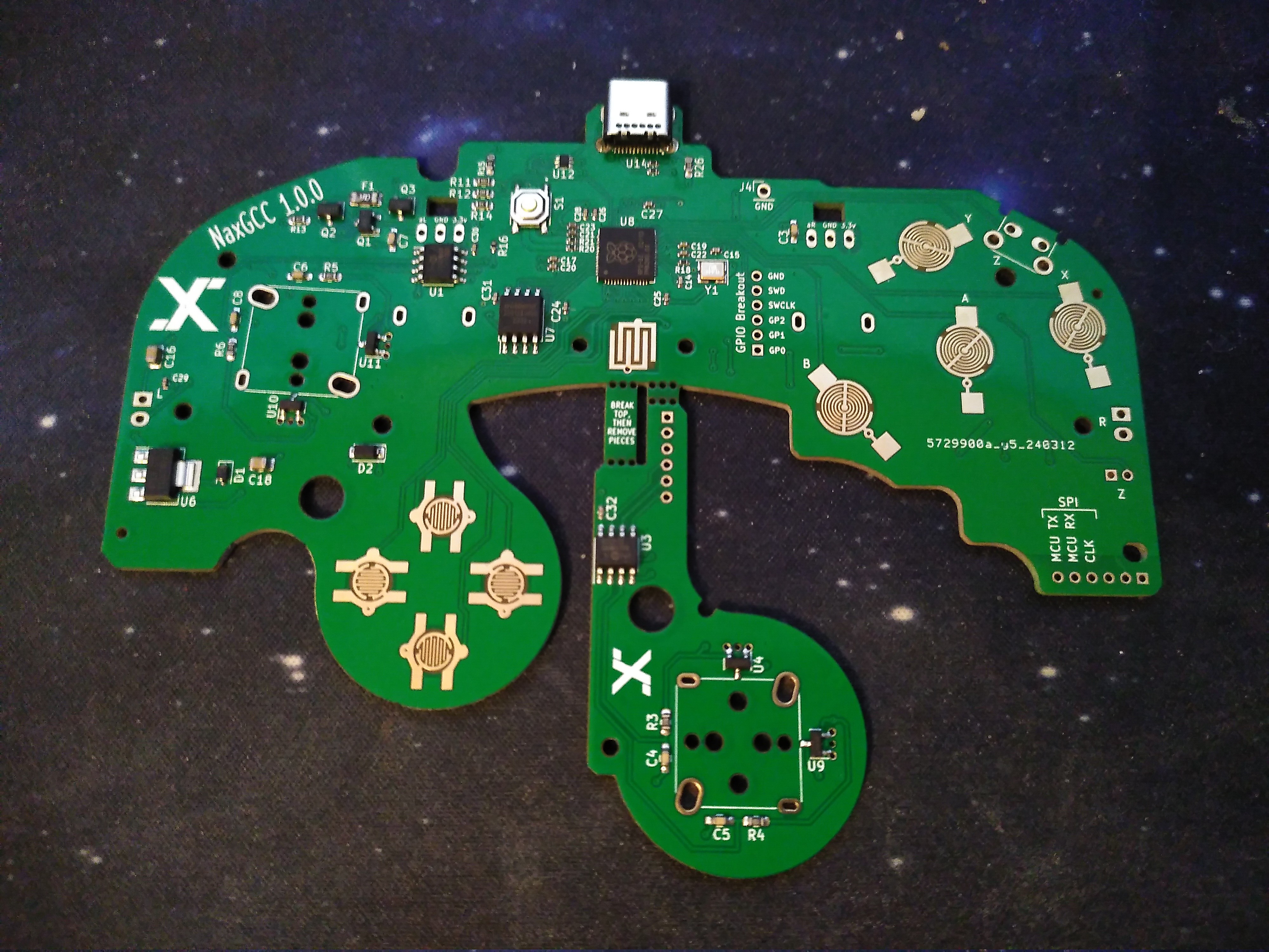
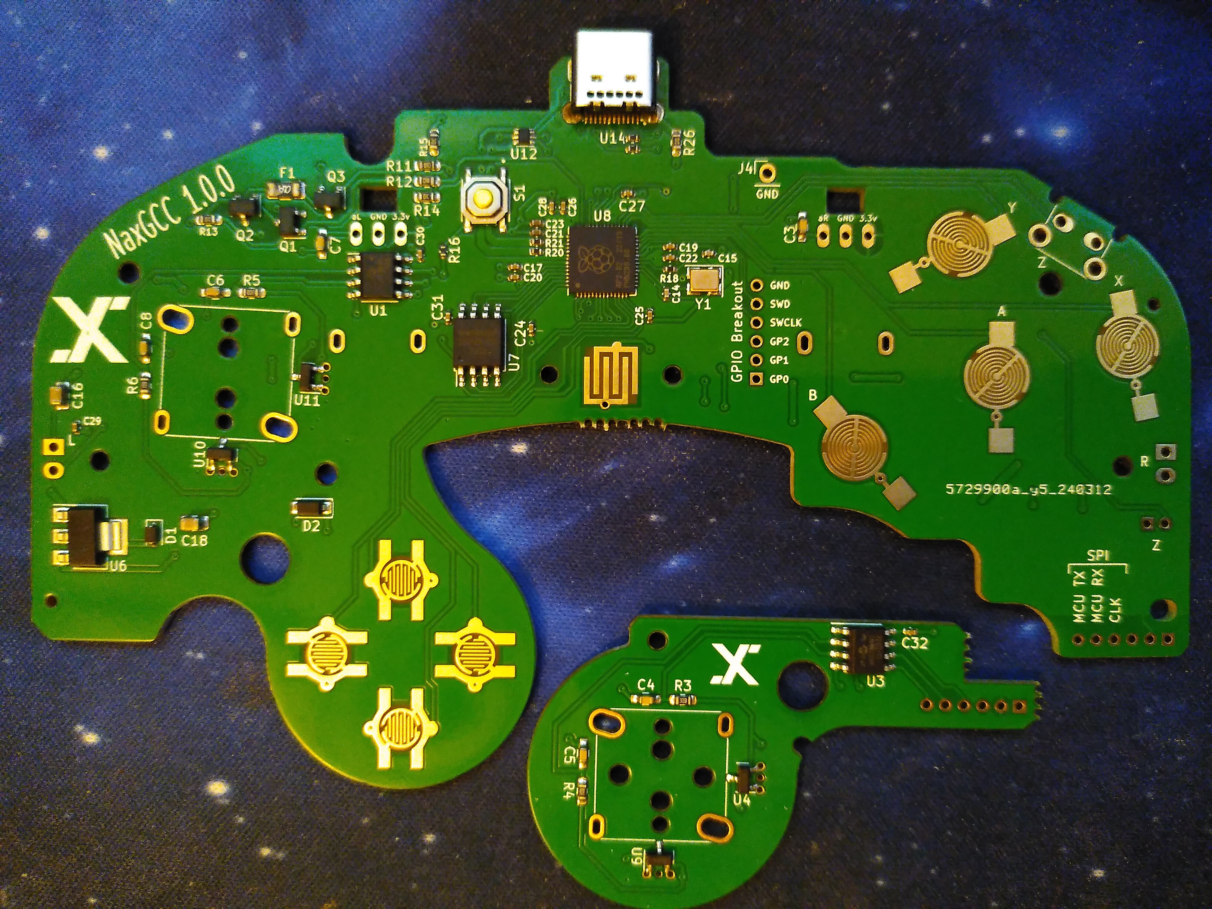
Hardware Assembly
This is an illustrated guide to making a NaxGCC, using photos taken of a NaxGCC board version 1.0.0.
Assembling a NaxGCC is conceptually very similar to assembling a Phob 2.0, therefore many sections of this guide (including images) have been taken straight from the official PhobGCC assembly guide. Note that though some images may depict a PhobGCC, the steps are still applicable to the NaxGCC. In parts where the hardware differs, newer images have been used.
Though the NaxGCC is very beginner friendly, and it is possible to build a NaxGCC as your very first soldering project, it is still recommended to get a soldering practice kit to build your physical understanding of the soldering process with before you start.
Tools
It's possible to work with cheap tools and supplies if you're very skilled.
But if you cheap out on solder or soldering iron "because you're just a beginner" you will be in for a lot of pain and suffering.
Required Tools
- Temperature-controlled soldering iron with a moderate size chisel tip. DO NOT USE AN UNCONTROLLED TEMPERATURE IRON!
- Flux-core solder, ideally no-clean flux (Sn63Pb37 melts at a lower temperature, SAC305 is nontoxic and flows better)
- No-clean rosin flux paste (not to be confused with solder paste)
- Tri-Wing screwdriver and small JIS driver set (Phillips drivers can strip screws)
- Sharp tweezers
- Solder sucker (or more sophisticated desoldering tool)
- Vise or PCB support (the alligator clip kind is not very useful)
- Multimeter for debugging
- 90%+ rubbing alcohol and cotton swabs
Suggested Tools
- Anti-static mat / grounding strap
- Fume fan
Parts
Some of the parts are taken from a donor Gamecube controller, while others must be sourced new.
New Parts
- NaxGCC board (includes C-Stick daughter board)
- 4x magnets (recommended: 3x3mm cylindrical neodym magnets)
- 3D-printed magnet holders
- superglue
- optional 2x trigger paddles from the PhobGCC project
- optional 4x D-pad buttons
- optional 4x mouse buttons for
ABXY(assembly not depicted) - optional 1x or 2x mouse buttons for triggers (assembly not depicted)
- wire
Parts Harvested from Donor GCC
Not counting stick caps, buttons, etc.
- 2x stickboxes
- rumble motor (or use a cellphone rumble)
- rumble bracket (or source your own 3D-printed one)
- Z-button switch (or source your own alternative one)
- trigger paddles with attached wires (or use the ones from the PhobGCC project)
- top shell (or use a custom 3D-printed one)
- bottom shell
Build Process
GCC Part Harvesting
Begin by taking apart the donor GCC using a Tri-Wing screwdriver.
Remove the motherboard.
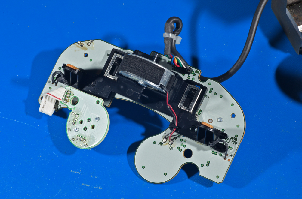
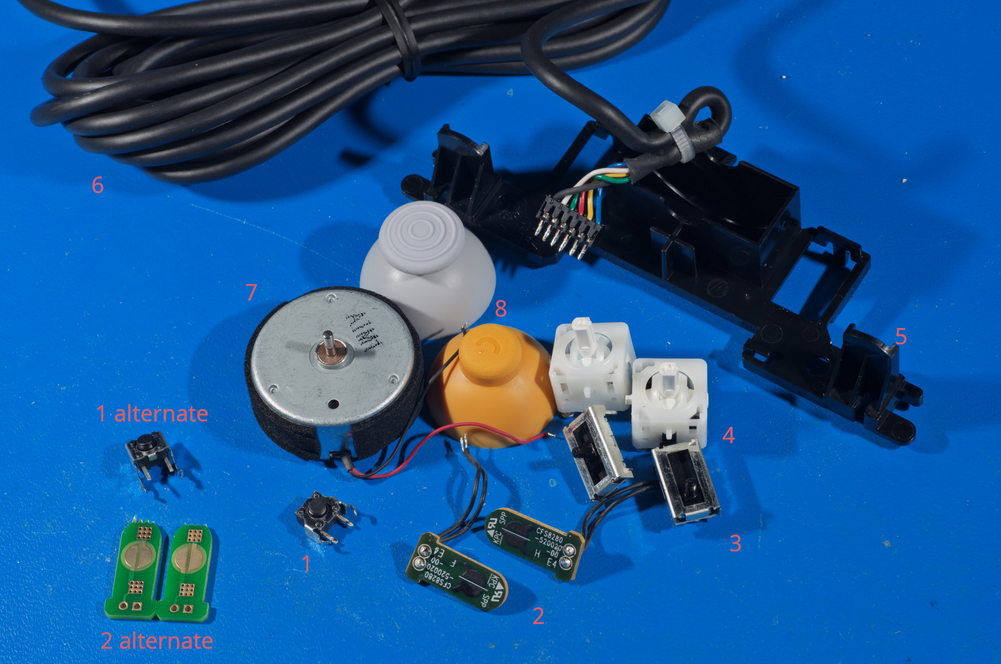
You will want to remove the following parts from it:
- Z button (or supply your own alternate as shown)
- Trigger paddles (or use PhobGCC ones as alternates as shown)
- Trigger potentiometers
- Stickboxes (preferably T3)
- Rumble bracket (or supply your own 3D-printed one)
- GCC cable (or supply your own)
- Rumble motor (or omit it, or use a cell rumble)
- Stick caps
these are not used in the NaxGCC presently, because SSBU doesn't respond to analog trigger signals, but you may attach them anyway for future-proofing purposes
If you're not familiar with removing the stickboxes, you can stick the points of tweezers between the stickbox and the potentiometers to unclip the potentiometers. Then, use a JIS #0 screwdriver to unscrew the screws from the bottom of the stickboxes.
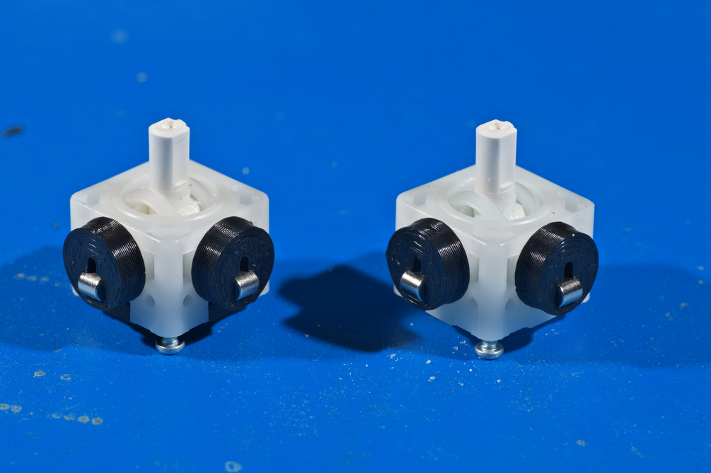
Magnet Mounting
Like the PhobGCC, NaxGCC uses sensors mounted perfectly flat on the board. You will need to mount magnets on the stickboxes using 3D-printed magnet mounts in order for the sensors to read the stick positions.
When using 3D-printed magnet holders, we strongly urge you to superglue (cyanoacrylate) the holders to the stickbox pegs. It's easiest to do this early in the process so that the superglue cures sufficiently before
First, clean the grease off the stickbox pegs with isopropyl alcohol and wipe off the alcohol. Do not allow it to evaporate on its own, or it will simply redeposit the grease back down.
Then, optionally, you may scratch up the pegs using a steel pick or a razor blade. This exposes clean, fresh plastic for gluing to.
Do not apply superglue to the pegs!
Press-fit the magnet holders over the pegs, making sure that the hole for the magnets is offset downward.
The ideal offset may vary with different magnets, and different magnet/offset combinations may result in slightly different stick behavior.
Coat the inside of the magnet hole, and the top of the peg, with superglue. Thin superglue is preferred.
Be very sparing with superglue so you do not contaminate the stickbox!
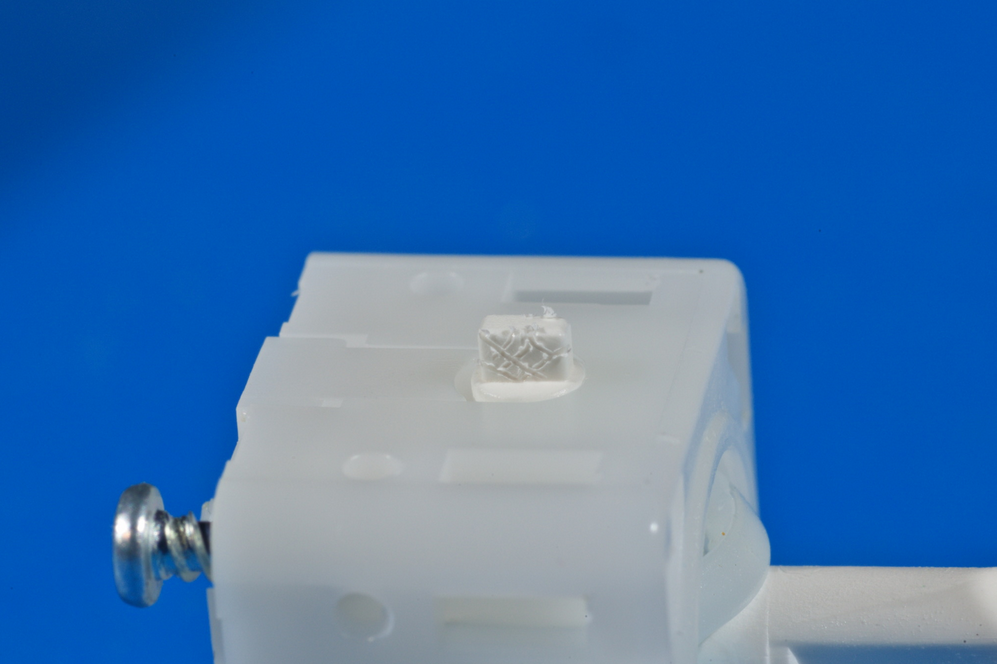
Insert magnets into the magnet wells, making sure that the magnets are all oriented horizontally.
If the magnets are not horizontal then the stick will not function.
The magnets should be inserted to have their polarity aligned, that is to say if you were to remove the magnet mounts and hold them opposite each other, they should attract one another without attempting to flip orientation. Mounting them differently may cause cross-axis interference, which can (and probably will) lead to erratic stick behavior. The NaxGCC firmware is especially sensitive to this.
If you're inserting your magnets into already-glued magnet mounts, you may use a third magnet to ensure you're inserting both the same way. The third magnet should attract to both magnets you're inserting the same way around, without attempting to flip orientation. It is recommended to mark the third magnet, so you don't forget which way it should be oriented.
If you wish, you can add extra superglue on top of the magnets to ensure they are securely held in place, though this is not absolutely necessary.
Set the stickboxes aside to cure.
Trigger Modification
The NaxGCC only makes use of the digital trigger paddles, as such it is highly recommended to modify the L & R triggers to include a 3D-printed stopper in order to raise their height and make them more comfortable to use. You can find the 3D-printable stopper files in the NaxGCC-HW git repo. Simply print two stoppers (or have someone print them for you) and slide them into the hole at the bottom of the triggers.
Be careful when reassembling the controller, as slightly depressing the triggers may cause the rubber to be pushed out.
Board Preparation
The C-Stick daughter board comes attached to the main NaxGCC motherboard. You will have to remove it.
To do this, first simply snap it off at the motherboard side. You can use your bare hands, but be careful to avoid touching the button contacts, such as for the Start button, or you may contaminate them with oil (not a big deal, but you'll have to clean it off with isopropyl alcohol afterwards, or risk the buttons not functioning reliably).
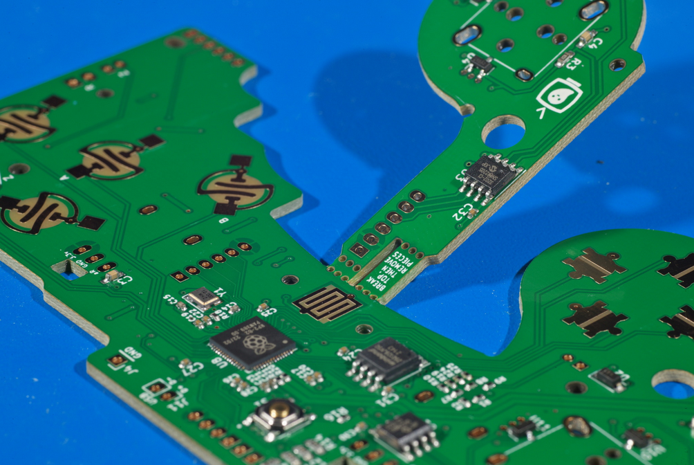
Then, break the two "mousebites" off of the C-Stick daughterboard using pliers. Note that one is longer than the other; this is normal.
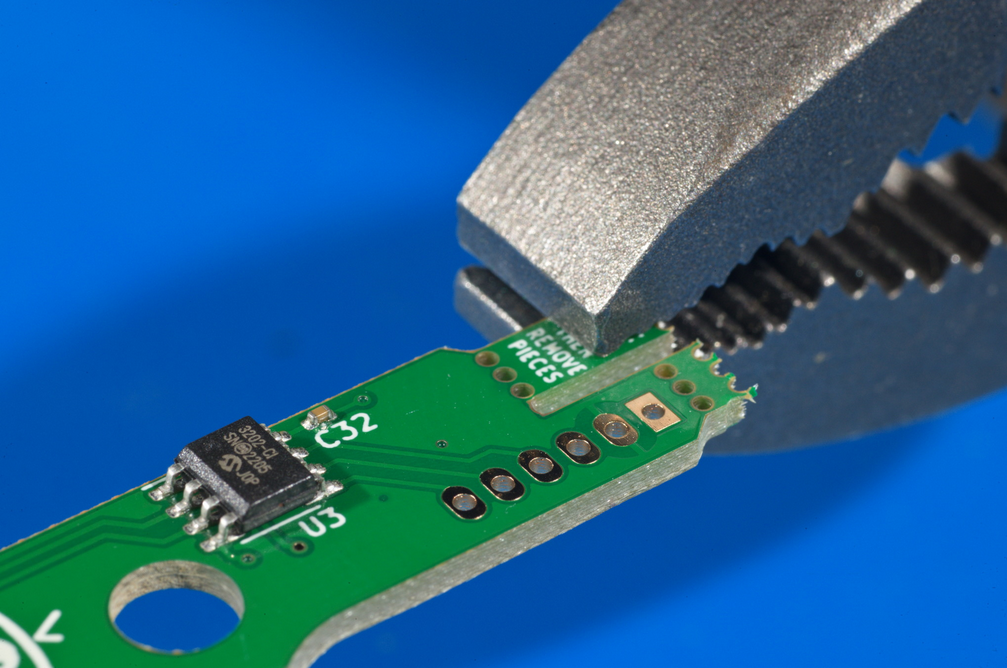
This should be the result.
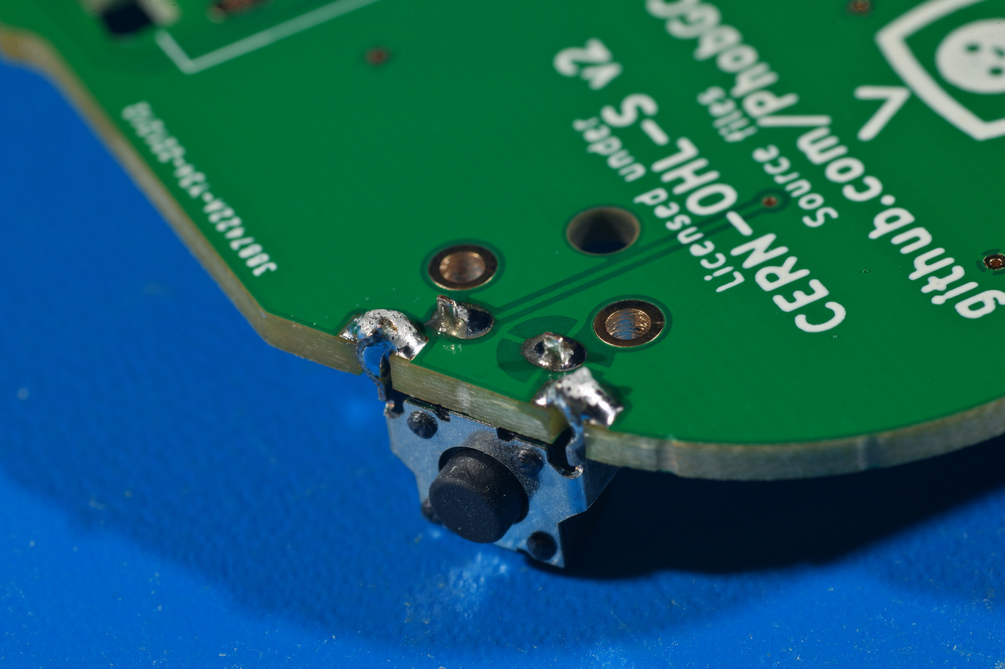
Z button Switch Soldering
The first soldering step is to solder the Z button switch on.
Make sure to put the button on the top side of the board where the silkscreen outline of the component is, not on the back.
Also make sure that the switch stands perfectly square to the board, or the board may not fit in the controller shell properly.
If you are using a Z button switch harvested from an original GCC, you can ignore the two large circular holes.
Trigger Potentiometer Soldering
Currently, trigger potentiometers are not used in the NaxGCC, but you may attach them for future-proofing purposes. To do so, follow the PhobGCC assembly guide.
Trigger Paddle Soldering
If you are using OEM trigger paddles, you may skip this step.
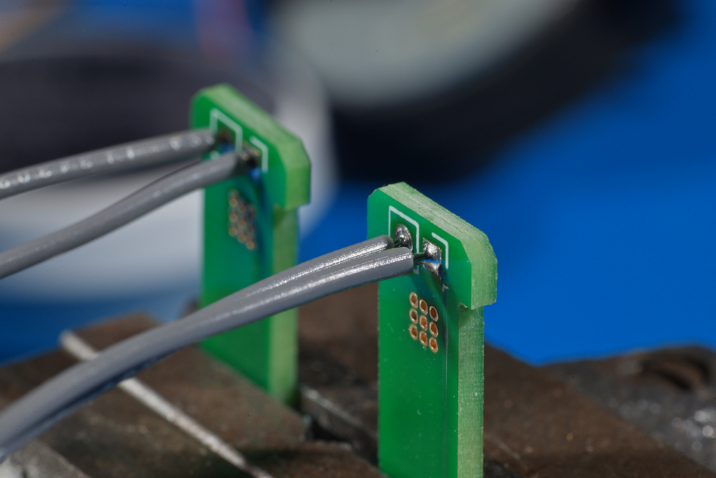
If you are using PhobGCC trigger paddles instead of OEM, you will need to solder wires to them yourself.
Cut four pieces of wire to about 38mm long and strip the insulation off the ends.
Apply flux to the ends of the wires, making sure not to cause them to fray if using stranded wire.
Hold the trigger paddles in a vise and apply solder to fill the through-hole pads with solder.
Then, heat the front side of each through-hole with your soldering iron to melt it, and insert the fluxed end of the wire from the back side of the hole where the silkscreen markings are.
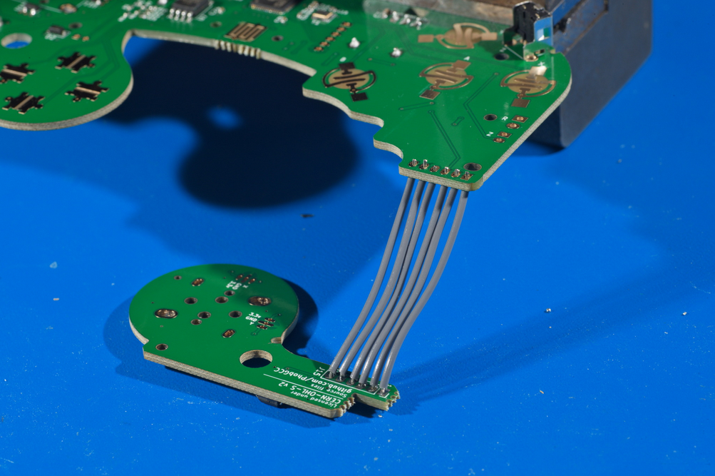
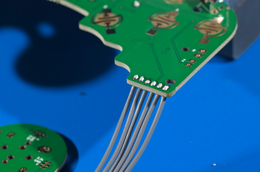
C-Stick Cable Soldering
The C-Stick needs six conductors connecting it to the main motherboard.
You will have to provide your own wire for this, though there may come to be brand-new ribbon cables available that may suit the purposes. Any such ribbon cables should be between 1 and 1.5 inches long (25 to 38mm) and must be 2 millimeter wire spacing. We strongly discourage the use of ribbon cables harvested from other controllers, as poorly folding previously-used ribbon cables has been a major cause of issues with PhobGCCs in the past.
Cut six pieces of wire to about 38mm long and strip the insulation off the ends.
Apply flux to the ends of the wires, making sure not to cause them to fray if using stranded wire.
Follow the same procedure as with the trigger paddles to solder the wires to the C-Stick daughter board. Note that this is the side with silkscreen around the through-holes.
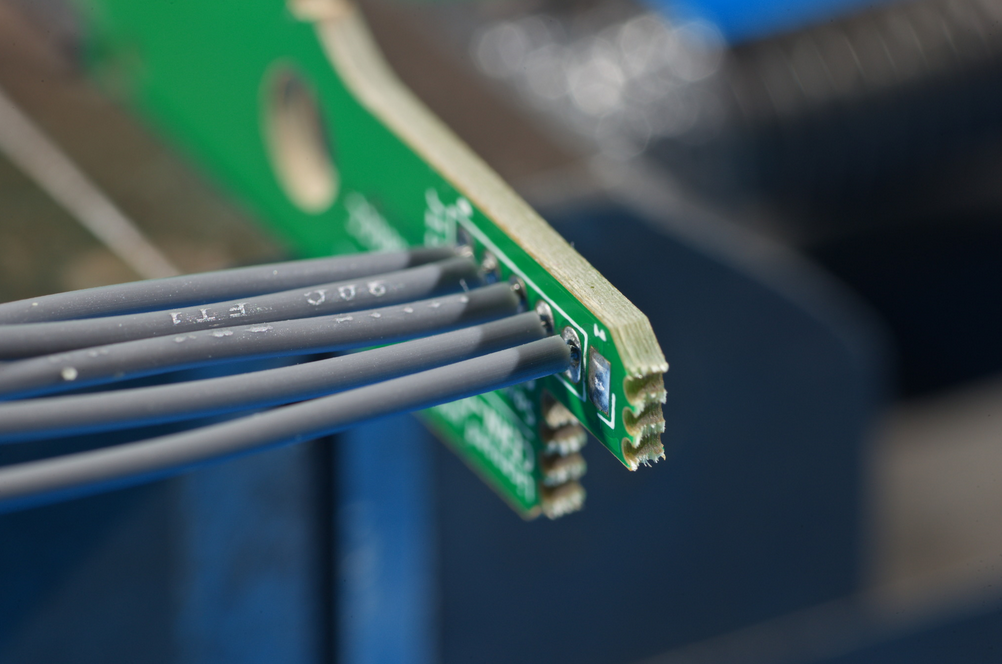
For these especially, if you are using individual wires, it is highly recommended that you make their lengths as consistent as possible, and solder them such that the insulation ends at the same distance from the C-stick daughterboard.
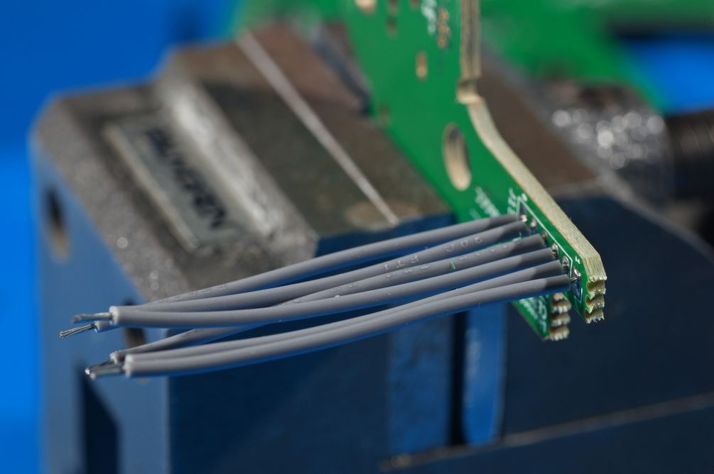
The uniform length helps when you are inserting the wires into the motherboard.
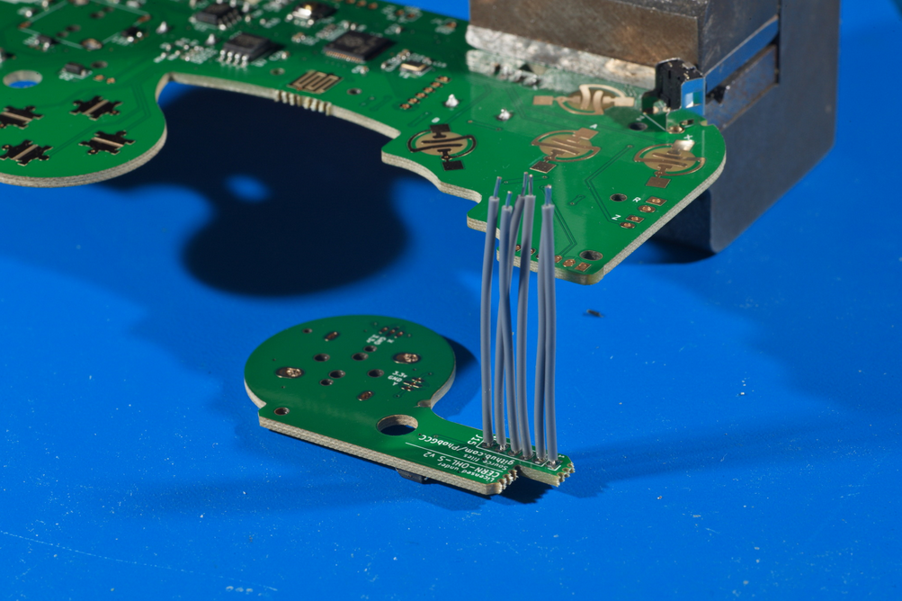
Support the motherboard above the C-Stick daughterboard with the daughterboard oriented like this.
If you flip it around, the C-stick will not function at all.
Insert all of the C-Stick wires into the motherboard.
Make sure that all of the wires are straight and none of them are crossed, or the C-Stick will not function.
Then solder the wires.
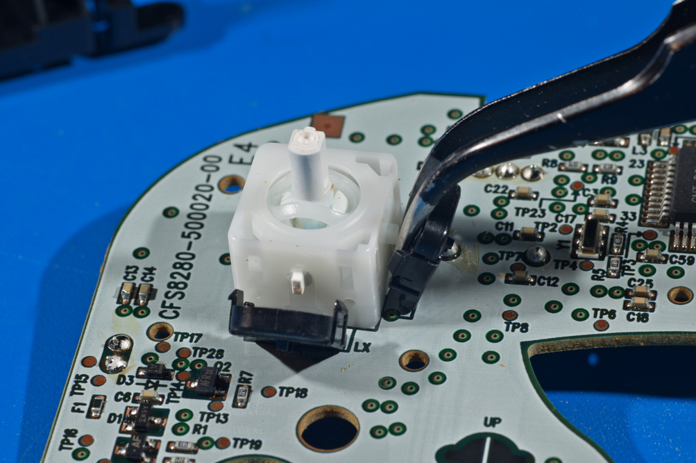
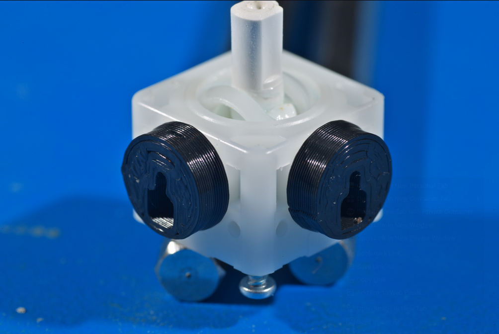
Stickbox Installation
Install the stickboxes on the motherboard and the C-Stick.
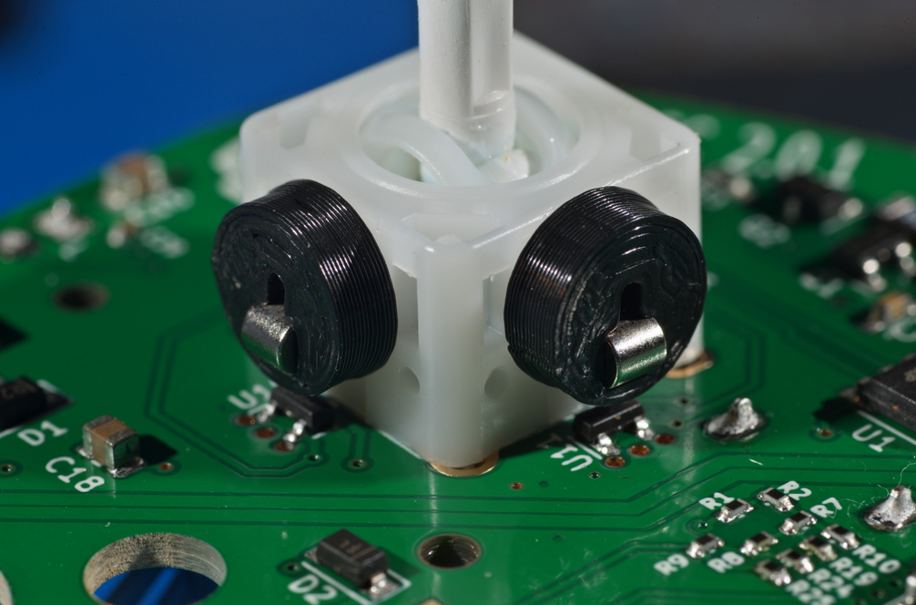
You must have the magnets mounted above the 3-legged SMD Hall-Effect sensors.
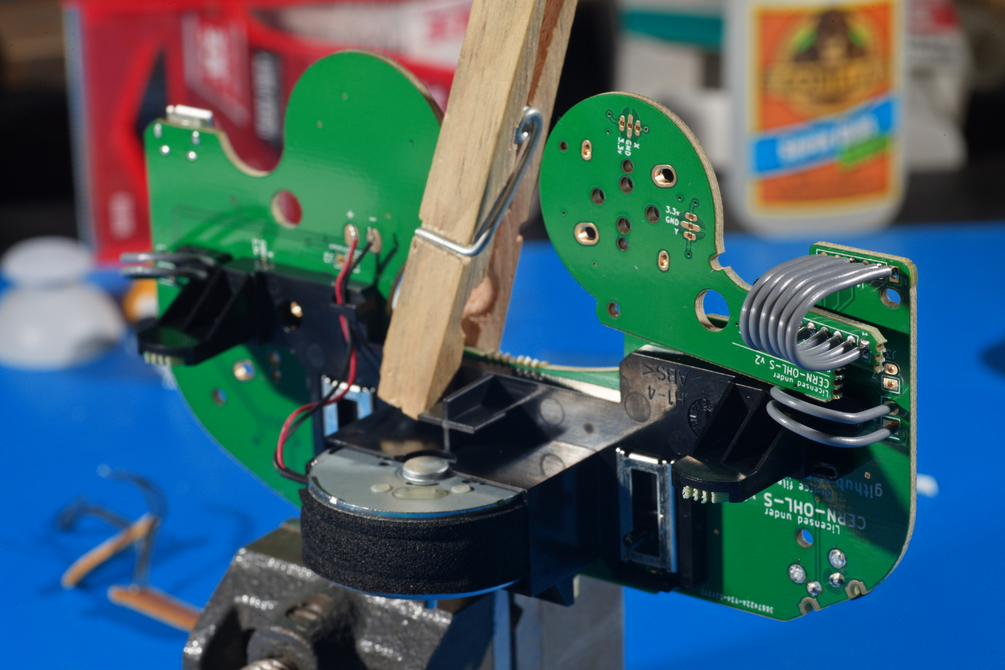
Trigger Paddle Soldering
Insert the trigger paddles into the rumble bracket (whether OEM or third-party), ensuring that the contacts on the trigger paddle are visible. Route the wires out the slots on the back of the rumble bracket.
Then mount the rumble bracket to the motherboard. In the image, there is already a rumble motor in the rumble bracket, but that can be left until later. The rumble bracket can be held in place using a clothespin.
Tuck the wires from the trigger paddles into their respective holes on the motherboard.
For R, make sure not to mix up the holes with the extra holes for mouseswitch Z, which are nearby.
Then solder the wires in place.
Rumble Motor Soldering
Mount the rumble motor in the rumble bracket by inserting it into the rectangular box. Make sure that the shaft is on the side with the USB-C connector, and the motor is rotated so that the wires are on the D-pad side, close to the edge of the box. Solder the rumble motor wires to the motherboard, with the red soldered to the + pad and the black soldered to the - pad.
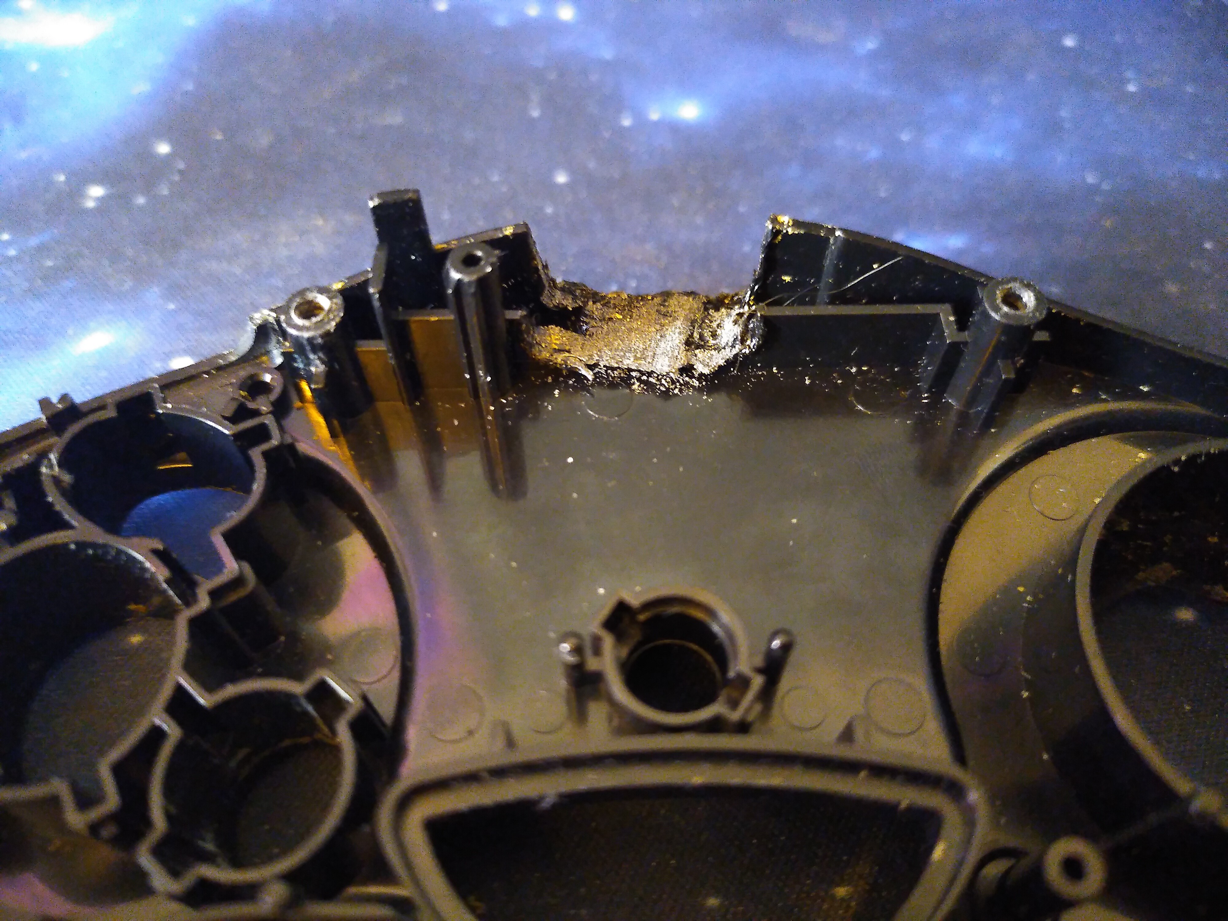
Top Shell Modification
If you're using a 3D-printed top shell, you may skip this step.
If you're using an OEM top shell, you will need to modify it to allow the USB cable to pass through. An easy way to do this is using your soldering iron. Simply melt away the extra plastic in the center of the shell, enough for the USB-C connector to fit through. It won't be pretty, but it'll get the job done.
More advanced modders, feel free to use a dremel or a drill to make a cleaner hole.
When melting or sanding, take care to wear breathing protection and work in a well-ventilated area. The fumes from melting plastic are toxic, and inhaling microplastics is not particularly good for your health either.
It is highly recommended to only do this with a soldering iron that has exchangeable tips, as the plastic will stick to the tip and reduce its usefulness for actual soldering. Conical tips are best expended for this, since they aren't very good at making surface contact for soldering anyway.
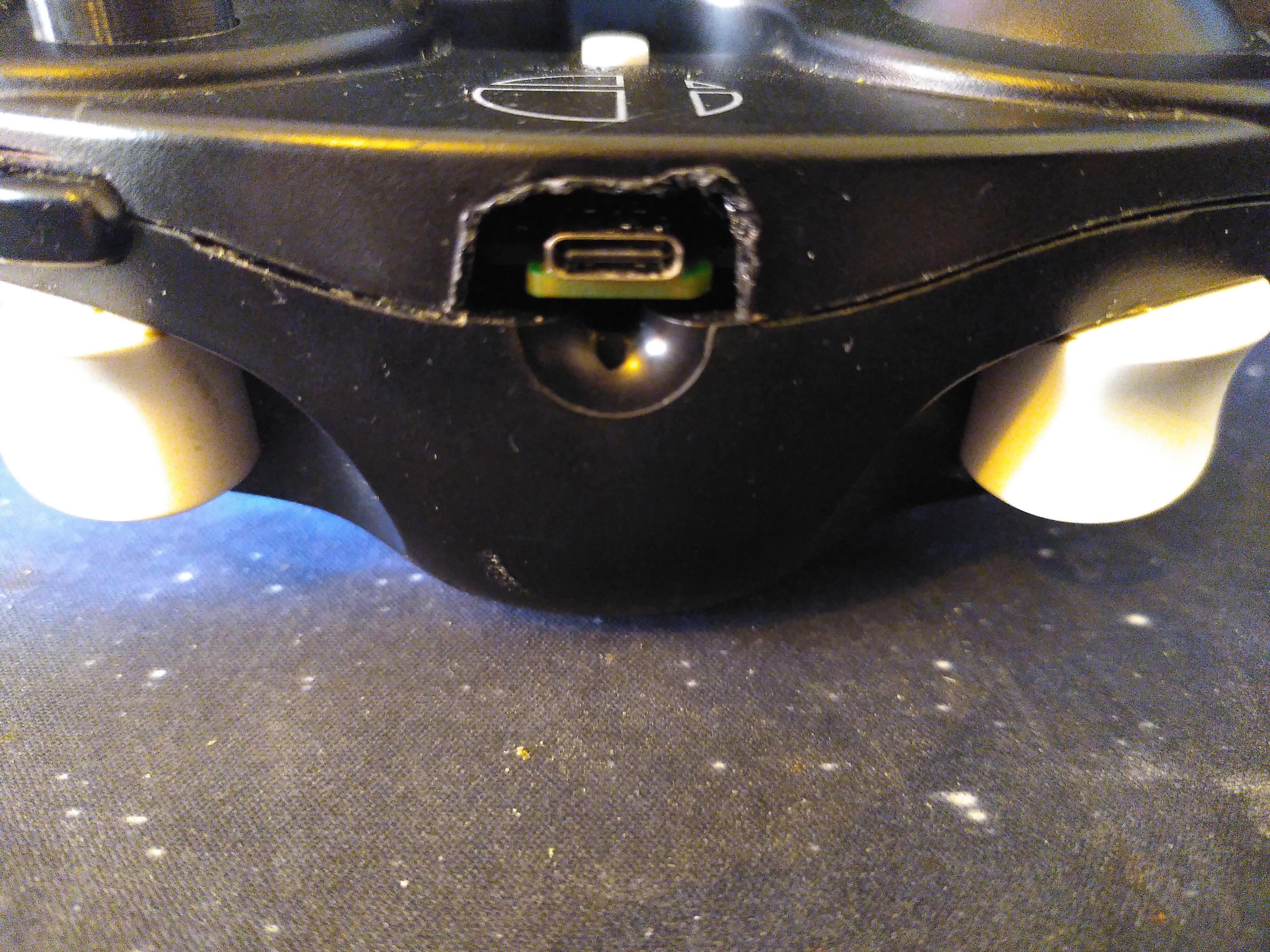
The end result should look something like this:
The USB-C port should be easily accessible from the outside of the controller:
Completion and Next Steps
Now your NaxGCC should be complete!
Reassemble your controller and head on over to the configuration guide to set up your controller to your liking.
Phob2.0 -> NaxGCC Conversion
Converting a PhobGCC using a Phob 2.0 board to a NaxGCC is a fairly straightforward process. The first thing you will have to do is flash the NaxGCC firmware to your Phob board. And that's it, your Phob is now a NaxGCC! Well, not quite yet.
You'll notice that the GCC cable no longer works. The whole point of the NaxGCC is to connect to the Nintendo Switch directly via USB, after all. To do this, you have two options:
OlyU (Preferred Method)
The OlyU is a small daughterboard for the PhobGCC that equips it with a USB-C connector at the back of the controller. This allows you to connect the controller directly to the Nintendo Switch, without the need for an adapter.
Minor soldering is required to attach the OlyU to the Phob board, and you will also need to make minor adjustments to the back of the controller shell to accommodate the USB-C connector:
The OlyU is an open source hardware project located here: https://github.com/sean44104/OlyU
Alternative Method
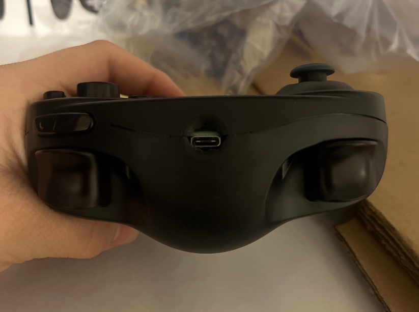
The alternative method involves modifying only your controller shell to allow a micro USB cable to connect to the Phob board. Usually this involves drilling or melting a hole in the bottom part of the shell, and then routing the cable through it.
You will also need a right-angle micro USB cable to connect to the Phob board. This is because the clearance between the board and the shell is very tight, and a regular micro USB cable will not fit. Alternatively, you can drill or melt a hole in the top part of the shell, but this is not recommended as it will make the controller less comfortable to hold.
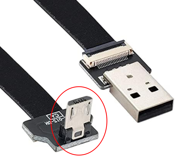
When choosing a right-angle micro USB cable to buy, keep in mind that the wide side of the trapezoid connector is going to be facing upwards when the controller is held normally. Most right-angle micro USB cables have the wide side facing downwards, so you will need to find one that fits this particular use case. Here's an example of what it should look like:
After flashing the firmware and making all the necessary modifications, it's now time to go ahead and configure your controller to your liking. Enjoy your new NaxGCC!