NaxGCC Buying Guide
So you want to buy a NaxGCC, but you may not know what to look for, and you may not know how experienced the seller is at making them. Since the NaxGCC is very similar in assembly to the PhobGCC, generally speaking, if you know a seller is experienced at assembling PhobGCCs, you can probably expect them to make a good NaxGCC as well.
However, it is still important to know what to look for, especially if you're buying a used controller, in which case you may not know who assembled it at all.
This guide aims to show you what to check for, ideally before you buy. If buying in-person, ask the seller to take it apart to show you.
Also note that a Phob 2.0 can be turned into a NaxGCC, and in this case special considerations apply.
Easy Checks
This section is for things that are simple to verify without technical knowledge: whether it works, and important part selection.
Board Version
As of writing, the latest and only version of the NaxGCC board is 1.0.0. If you see a version number other than this, it could be an unofficial fork with changes that may or may not be beneficial. Ask the seller about it.
Conversion Boards
If the controller is a Phob 2.0 that has been converted to a NaxGCC, ensure that the seller made sufficient modifications to the controller shell to allow a micro USB cable to connect to the Phob board during play. Otherwise, you won't be able to actually connect the controller to your console.
Functionality
Obviously, the controller should work. To verify functionality, it is recommended that you use Smashscope. Have a look at the Getting Started section of our configuration guide for more information on how to set it up.
The L & R triggers should not depress fully as with an OEM controller, but instead feel similar to the face buttons, with a short travel distance. They should register at full 255 values when pressed. Rumble should function as well (assuming a rumble motor is installed). You can verify this by pressing Z on the Controller Test screen in Smashscope.
The sticks should not be very noisy or jittery when held off-center, but jitter between two adjacent values is acceptable. Notches should have repeatable coordinates when entered from the same direction, though they may have different coordinates if entered differently (clockwise, counterclockwise, straight from the center).
The controller should be set up so that it doesn’t have snapback. You can test this in game, but ideally you can run Smashscope and make use of its oscilloscope. Consult the Beginning Calibration section of our configuration guide for more information on what it's supposed to look like.
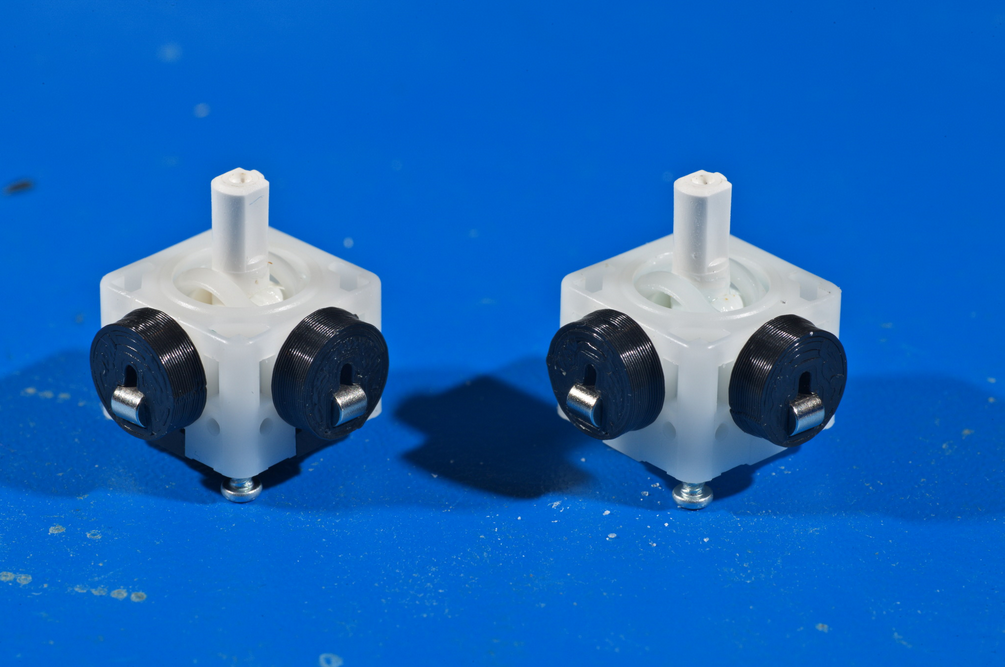
Stickbox
The stickboxes which contain the stick mechanism should be T3, which are entirely white plastic and mounted with two screws on the underside of each.
T1/T2 stickboxes, which have metal frames around plastic innards, are far more prone to wear and becoming loose. Additionally, they are soldered down, making them difficult to replace. This effectively limits the lifespan of a NaxGCC.
C-Stick Board
The C-Stick board should be a NaxGCC one with magnets, rather than an OEM C-Stick board with potentiometers. A Phob 2.0 daughter board can be used, and Phob 2.0.5 daughter boards are guaranteed to behave the exact same as a NaxGCC one.
The NaxGCC will not function with an OEM C-Stick board, or an earlier-generation Phob daughter board.
USB Cable
If the seller included a USB-C cable, ensure that it stays in place when inserted, doesn't fall out easily, and doesn't wobble. The Nintendo Switch is very particular when it comes to having a stable connection, and a loose cable can cause the controller to disconnect during play.
Ideally, you should be able to hang the controller from the cable, give it a good few shakes (not like Hercules, however), and it should not come loose. There should be some force required to remove the cable, and you should feel a click when inserting it. When wiggling the cable side-to-side, the controller should not disconnect (test this on an actual Nintendo Switch if possible).
Intermediate Checks
Here is where we begin evaluating the quality of the work.
Soldering Workmanship
Shorts
There must be no connections made between pads that are close together. You should be able to see green completely separating the solder.
Solder Joint Shininess
It is commonly believed that solder joints are supposed to be shiny, but that mainly applies to leaded solder (Sn63 or Sn60), not lead-free solder (such as SAC305). Most commercial products these days use SAC305 or similar due to regulations, but Sn63 is still often preferred by hobbyists for its ease of use.
Ask your vendor what kind of solder the NaxGCC you are evaluating was made with before judging the joint quality by how shiny they are.
Solder Bonding
All solder joints should have the solder clearly sticking to both the component and the board in order to make a strong physical and electrical connection.
Solder Quantity
The entire pad on the board should be wet out with solder, but there ideally should not be enough solder to form a convex ball.
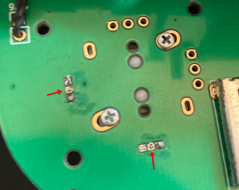
This is an example of a solder joint that has poor contact with the board and caused undesirable stick behavior.
Physical Workmanship
Stickbox Magnets
The magnet mounts on the stickbox should be firmly glued in place, and not come loose easily. A good way to test this is to use another magnet of the same strength and see if it can pull the magnet mount away from the stickbox. If it doesn't come loose, it's a good indicator that your controller will be able to sustain one or the other fall to the ground without the magnet mounts falling off.